DIY fan-coil heater
DIY fan-coil heater by Original Twist
Maybe the best fan coil heater regardless of price.
If you are wondering how a heat pump might (or might not) work at all with your old radiators and pipes this might give you the answer, and it won’t cost too much
Underfloor heating did away with horrible radiators, and we don’t want them back, so that just leaves warm air blowers such as kickplate heaters and bigger fan-coil units – i.e. hot water powered puffer heaters.
A kickplate heater can give an occasional guff of hot air and they cost under £200. However these neat little units aren’t perfect. They have to shift a lot of air through a small aperture so they are intrinsically noisy, draughty and the heat exchanger, or a filter, can clog with dust and pet hair fairly quickly. Larger fan-coil units are available but they aren’t so neat and they are much more expensive.
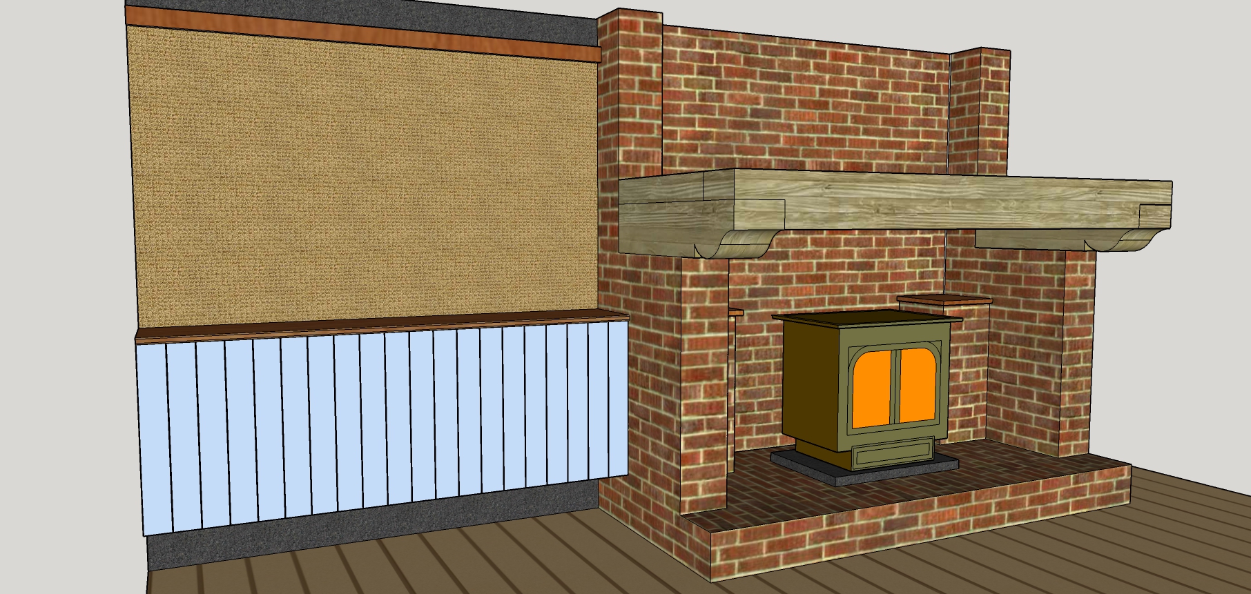
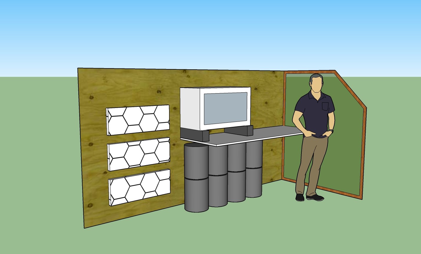
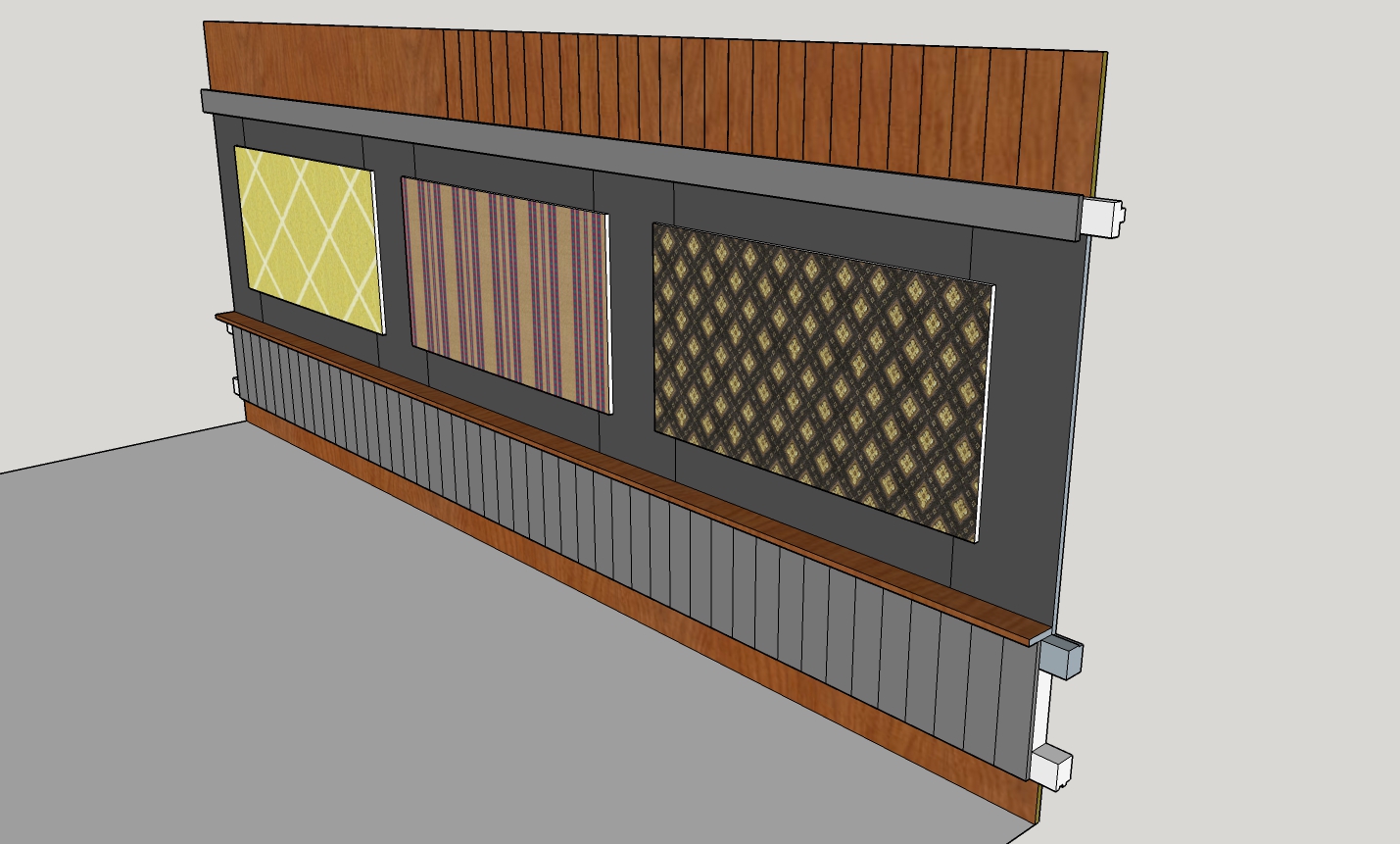
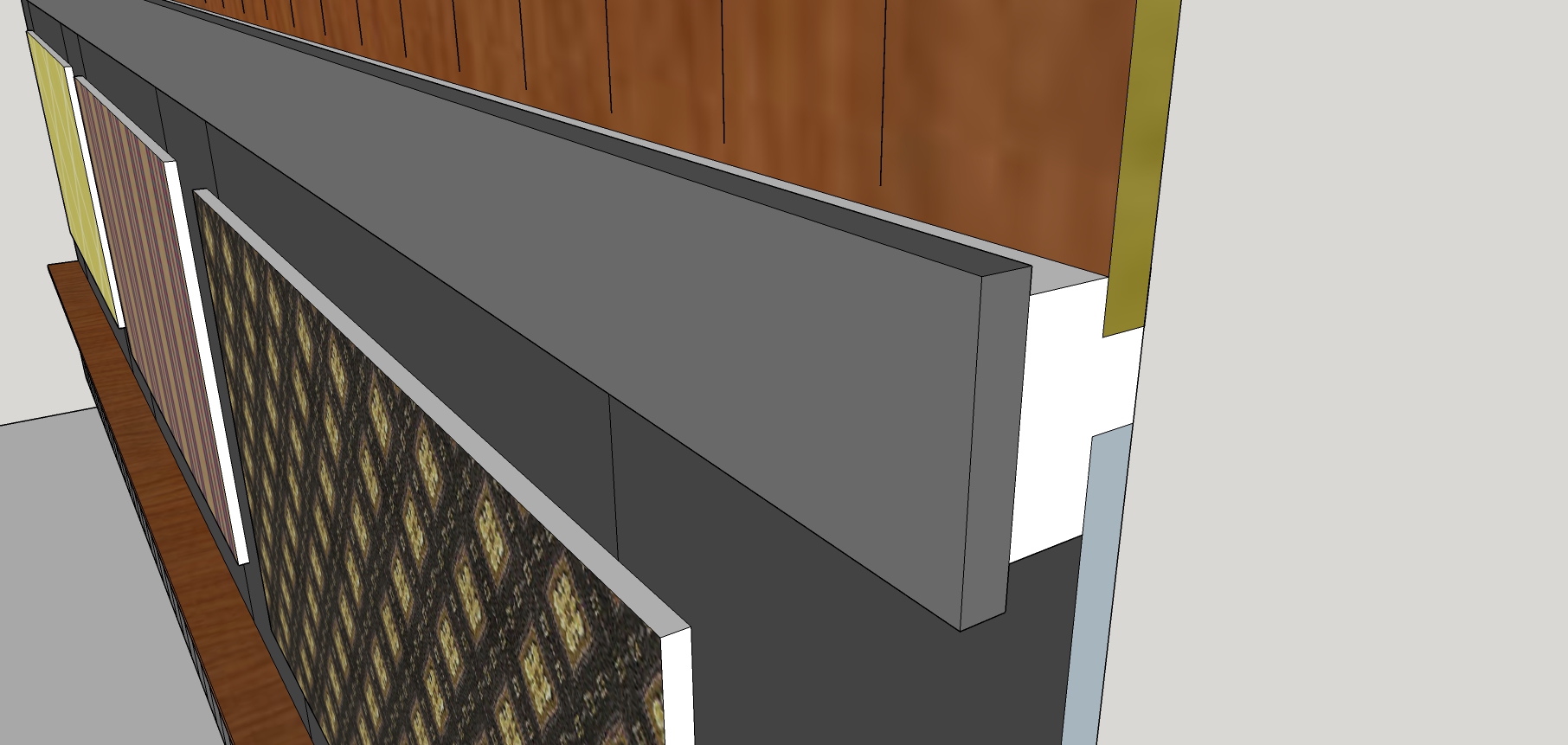
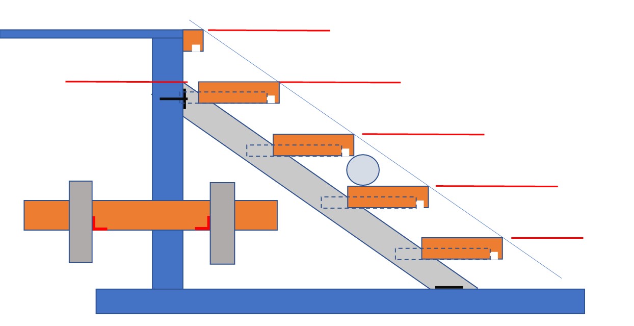
So here’s the Original Twist fan coil heater which is cheaper, quieter and more reliable. Double click this picture for a better look. Can’t see the heater? Neat huh.
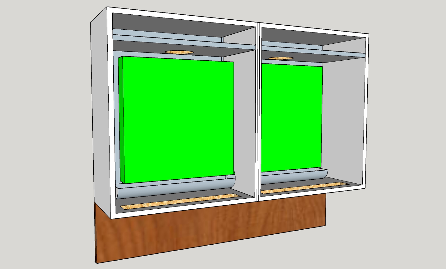
cupboards with fan-coil heater built in.
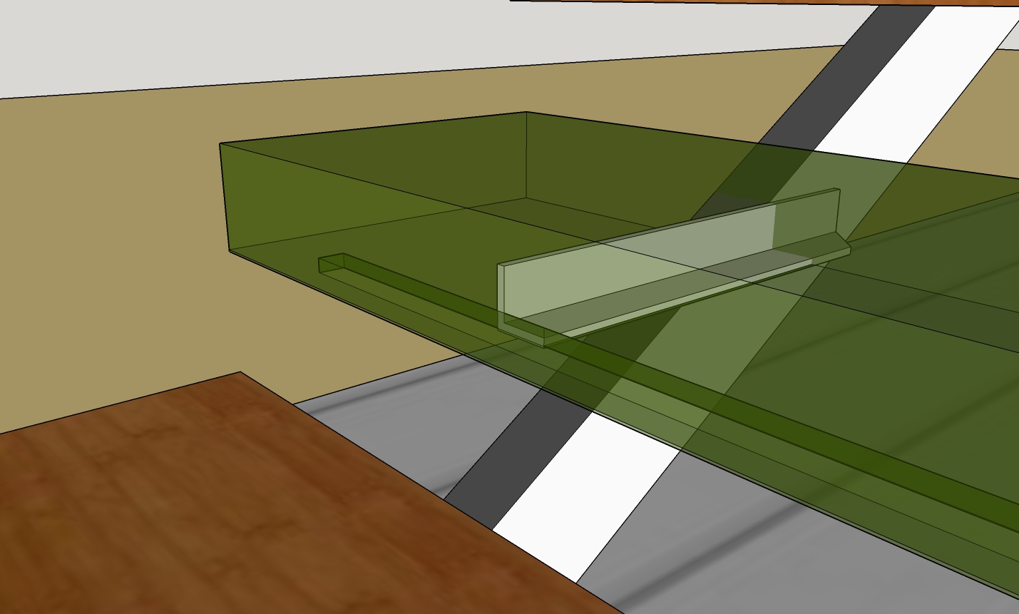
Lets assume that the low cupboard in this sketch is made of typical 720mm x 300mm kitchen carcass units, (just like your top cupboards). A pair of them (each 600mm wide) with a large slot cut out of the inner sides allows a 1000mm x 500mm x 70mm double radiator to fit inside (£48 Screwfix). Each of the top shelves is fitted just low enough to mount a 140mm fan from a computer (£10 – 20 Amazon etc) and these gently blow air past the radiator and out of the bottom. You can decide where the air inlet goes: probably top front but a wall panel channelling much warmer air from ceiling height is worth a thought. Note that this is much smaller and neater than the huge radiators you would be trading up to if you were trying to make a heat pump conversion work.
When paired with a suitable heat pump this unit can also do air conditioning, hence the length of plastic guttering under the radiator to catch any condensation. However, a separate mini-split aircon unit (a very cheap heat pump) which delivers hot or cold air could be a much simpler installation. Cold air flows across the floor so spreads around the house surprisingly well. You don’t need multiple sources like you do for heating.
UV-C disinfection: For many asthma sufferers this will be the main feature. Fitting UV-C tubes in the top sections will neutralise airborne bacteria and viruses, colds and Covid included. There are pros and cons about the ozone produced so I’d recommend thorough research before going ahead. UV light can damage your eyes so put kill switches on the doors and make sure there is no direct light escaping from the air inlet. Also, mount the fans underneath the shelves to keep the light off them. For the same reason it makes sense to put the transformer, relays, wiring etc screwed to the underside of one of the shelves.
A pollen filter, such as fitted to many cars, dropped over the low outlet will help too and can be Hoovered clean easily enough.
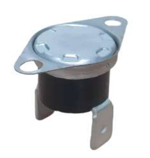
Controls: The fans can be switched on automatically when hot water arrives at the radiator. A bi-metallic thermostat switch will do the job simply enough – RS Components do one for about £8. It clicks on at 40C and off again at 25C. The switch can be glued directly onto the radiator near the water inlet. See picture below.
You’ll also need a variable resistor for speed control of the fans. They are 12v so you’ll need a power supply, another cheap PC component.
If you are doing the ‘off-peak energy storage for cheaper heating’ thing the hotter water is available for a boost start which could almost instantly make your bedroom warm for getting up. Fan-coils are best for bedrooms where you need fast response times; under floor heating takes ages to come on and then stays on too long.
Cleaning: Open the doors and Hoover it out – easy.
And that’s it really. A few simple components all easily obtained and making the perfect, reliable fan-coil unit. When turned down to essentially silent the fan pair will move about 100cfm and the heat output will be between 1 and 2kW depending on the water supply temperature. Turn up the fans to double this.
Noise? Just like putting your PC in a kichen cupboard so practically inaudible.
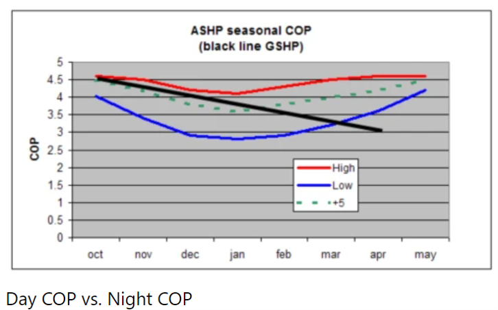
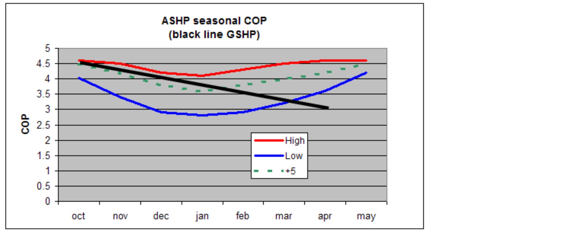
You might wonder why all this effort gives you anything better than the same radiator fitted as normal. The answer is that heat pumps don’t work efficiently at the 60c+ normally used with radiators. While under-floor heating is the best at very low temperatures a fan-coil unit works reasonably well at 40c. The only reason our unit has a radiator is that with all the fins in a double radiator you get a high surface area for not much money. The heat delivery couldn’t be more different. A radiator wafts hot air straight up to the ceiling where it tends to remain, replacement air then moves across the floor as a cold draught. A fan-coil, on the other hand, wafts warm air across the floor where it mixes with cooler air to give a faster and more comfortable heating experience.
Some extra mods
If you want to direct warm air somewhere in particular, patio doors for example, then a row of slats on the exit slot can send the air to the side. To go further with directed air flow you can also fit a duct or two to the bottom of the unit. This might be useful if you were trying to warm the air near those patio doors. In a new build you could fit a drain channel beside the doors (those ones with the clip-on metal tops) and blow hot air into the ends of the channel. That same channel could also be used as a handy route for the heating pipework and as an added benefit it makes the channel like a radiator in its own right.
MVHR reheat The MVHR system is essential in a modern house but as it is not 100% efficient it does cool the house slightly so using one of these fan-coil units as a re-heater is a neat and inexpensive route to perfection. If you have an MVHR system in mind you could run your return duct into the top of this unit with the benefit of hiding the outlet and getting a free blow from the MVHR fan.
What about the bathroom?
Now we’re talking. The perfect place to have hot air blowing especially when you are drying yourself. For a start turn the unit on its side so the air is blown from a vertical slot, then go one step further and have a pair of them so you step between them into a hot air blaster, like a giant Dyson hand dryer. Electricity in the bathroom! No worries there, keep it all 12v.
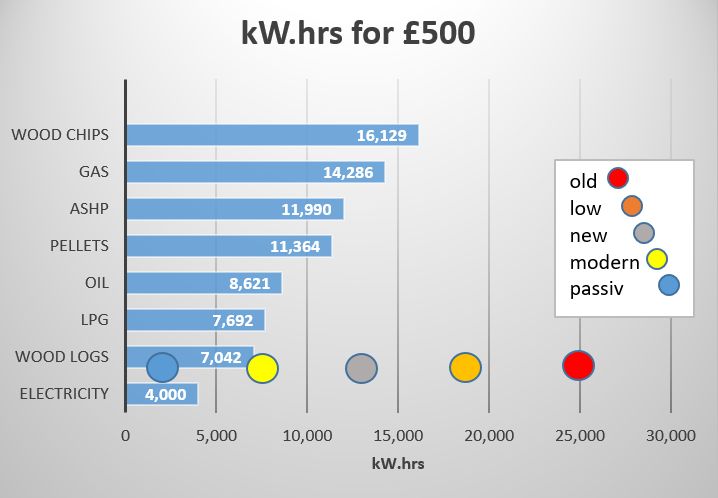
insulation matters
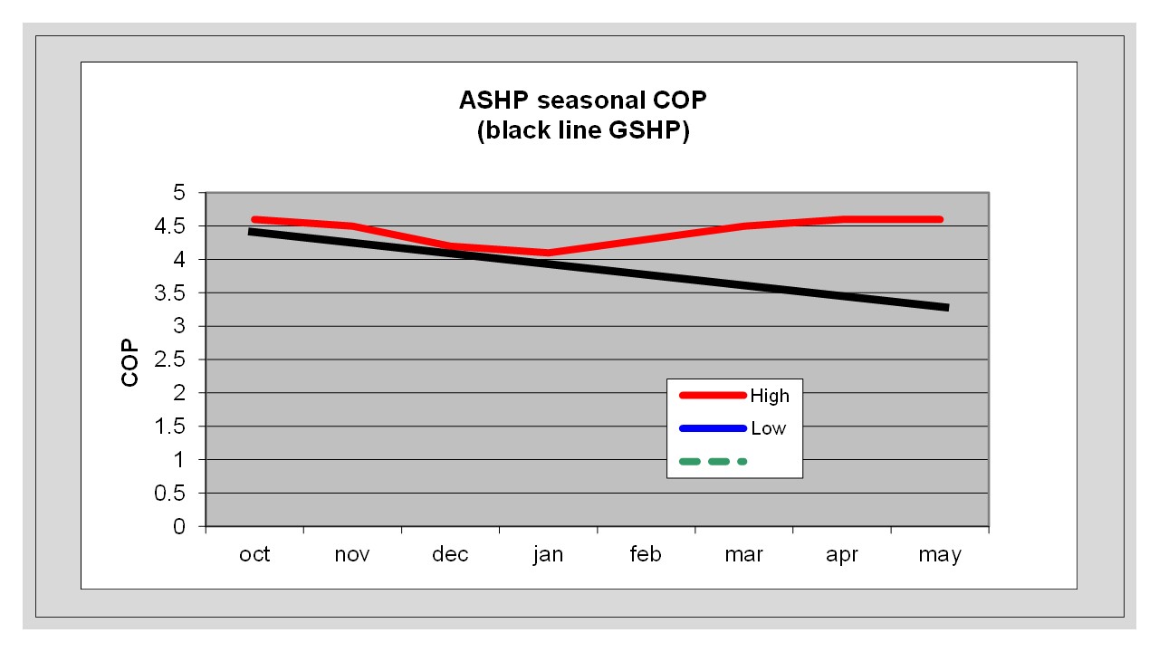
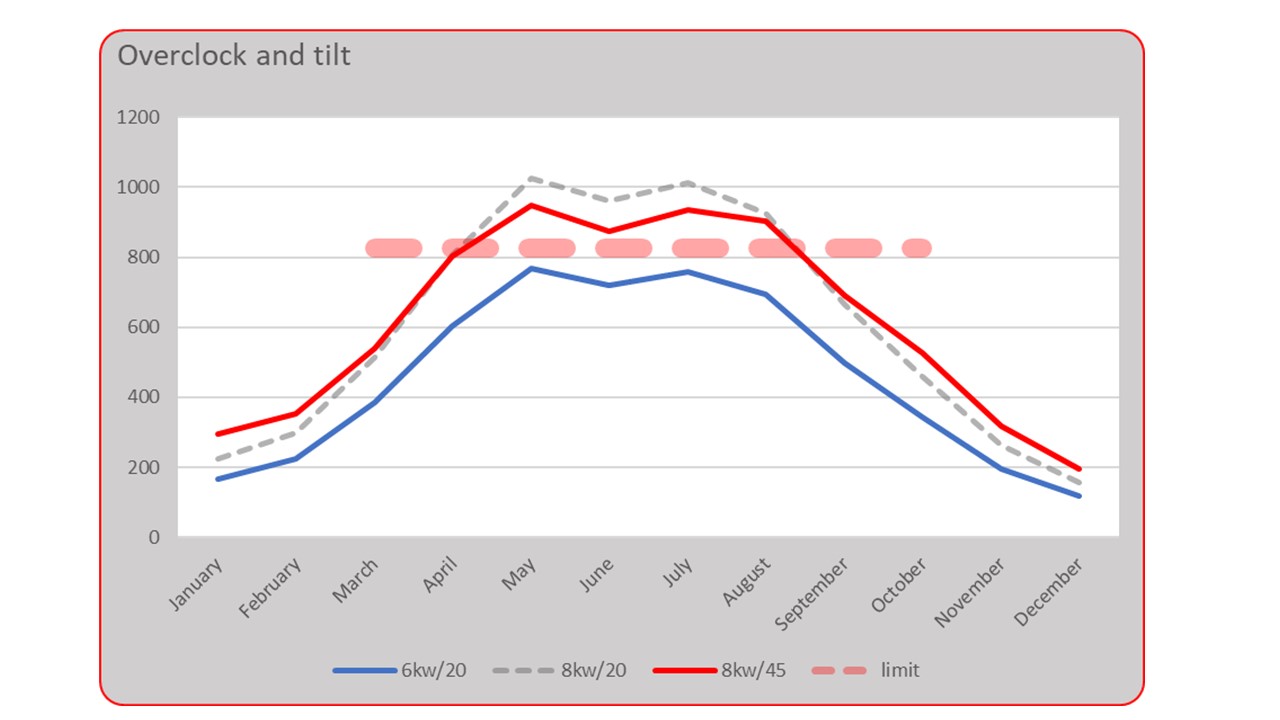
Have a look at this chart on heating costs for various house types to appreciate why a Passivhaus with a small heat pump and some fan-coil units could be the way to go. You’ll see that the ASHP can meet the Passivhaus demand for almost no cost. Indeed if the ASHP is connected to PV panels then the running cost of the house will be close to zero. This chart is out of date now but the message is the same.
I guess you might be in a state of shock now. Thousands saved on your heating strategy, the government might buy you a heat pump and air-conditioning can be a simple addition.
For more money saving shocks check out more building ideas on LIST OF POSTS.
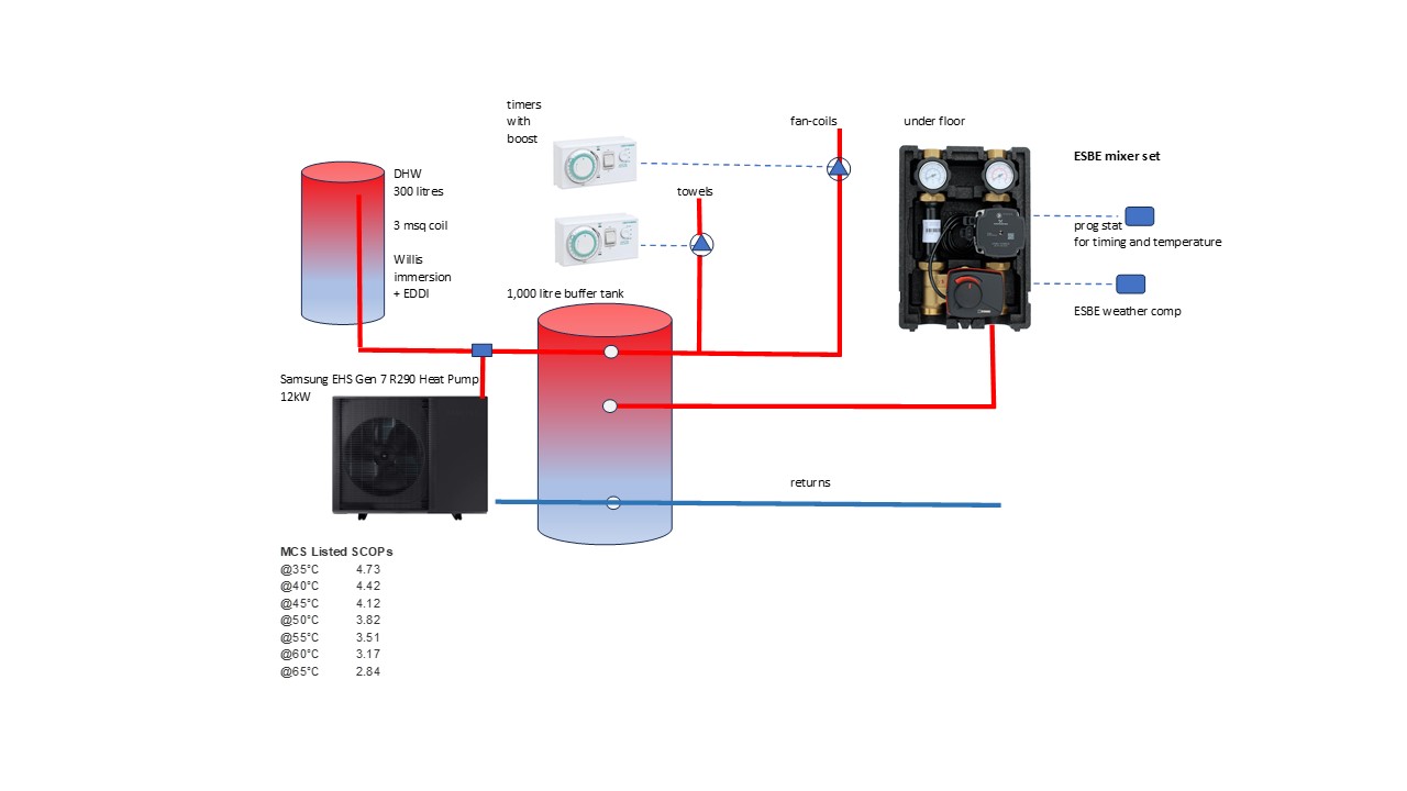
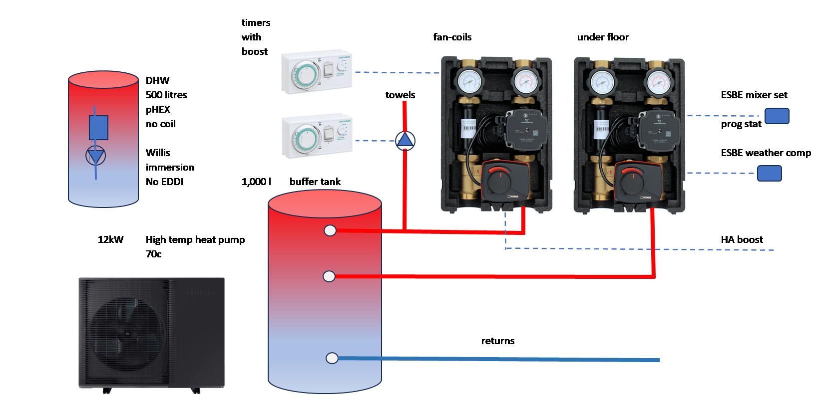
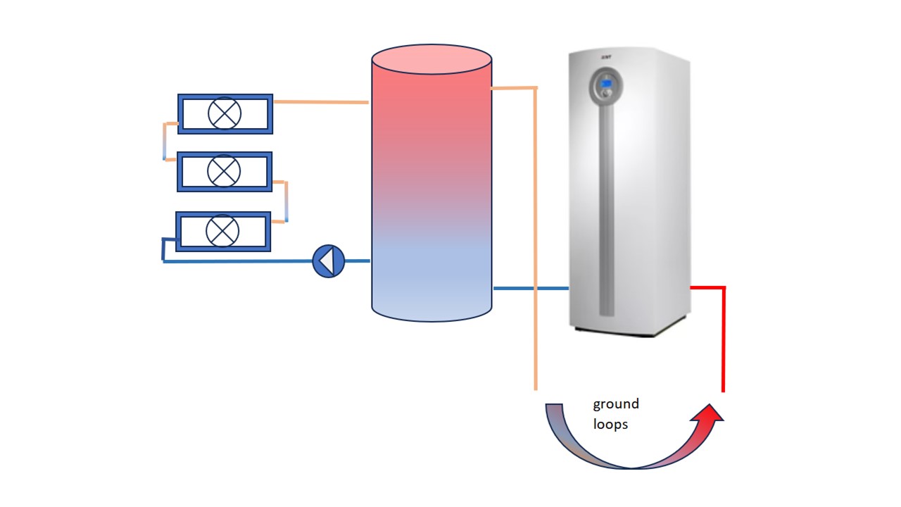
Don’t miss ideas on off-peak energy storage; see the Large house heat pump system
If you’ve built this unit please let me know on the comments form below. We’d all love to see pictures.


 a few times a day; all automated of course.


Leave a comment