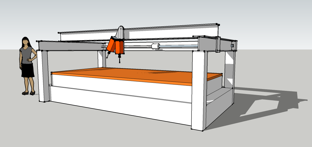
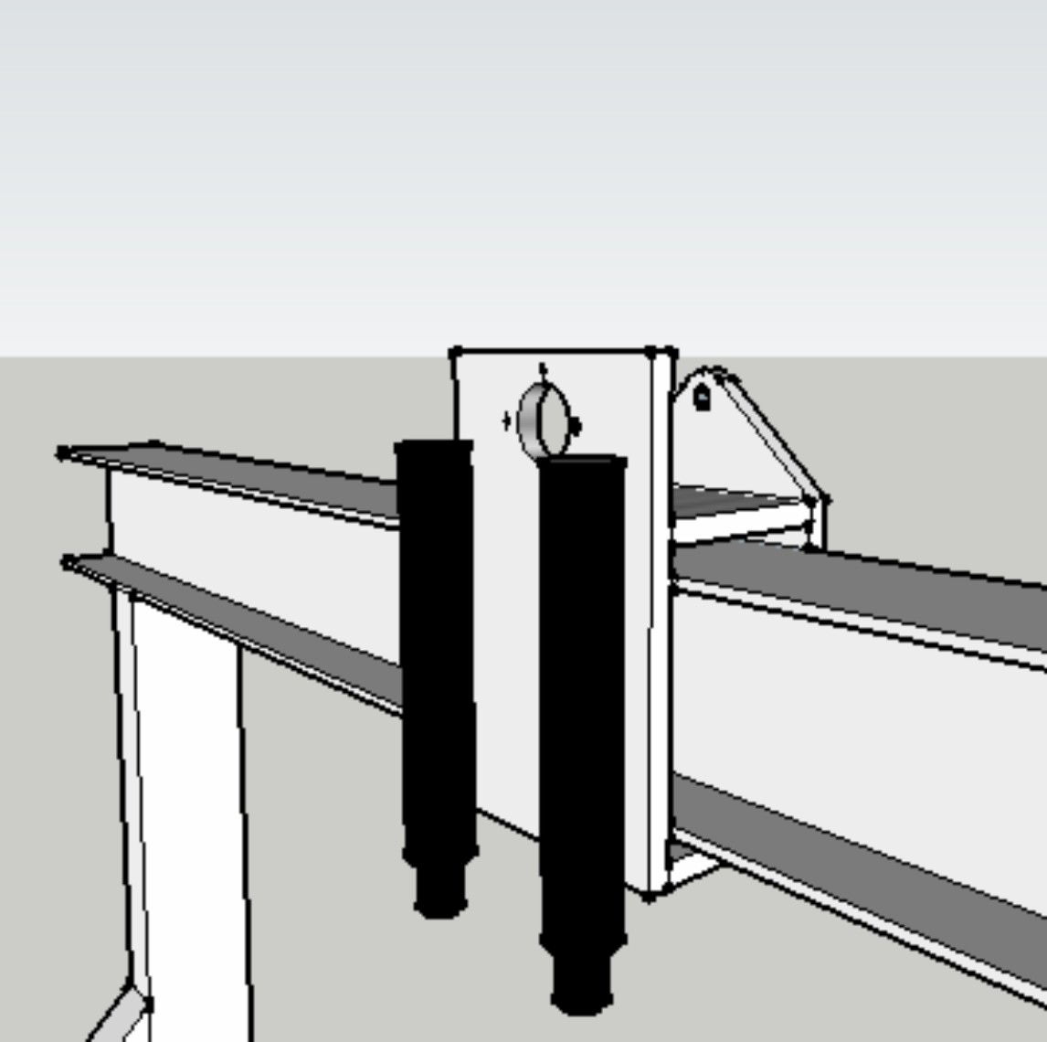
CNC router – Slide box and tool changer

Aluminium slide box

Aluminium slide box

tilting motor mount

tilting motor mount

Slide box: The basis is a wrap around box of thick aluminium plates enclosing the beam.
Each of the 4 plates has a unique function. The top and bottom plates are for the absolute location of the slide box; Turcite blocks for the heavy downward loads and vibration damping, ball bearing rollers only for lateral location.
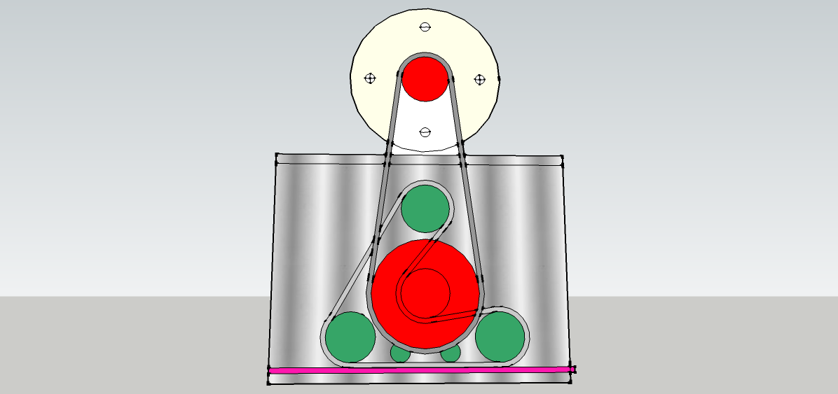
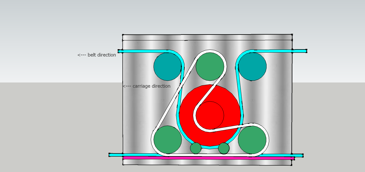
One vertical sideplate supports the entire drive mechanism – see picture. The drive motor sits over the top of the slide box and drives the big pulley on the outside. All the rest is inside the web of the RSJ ending up with the toothed belt driving onto the rack with a caterpillar drive to give more tooth contact. This plate is at the back of the machine and also supports a pair of Desoutter AFDK drills which just need a pulse from a 4mm air pipe to set them off on an automatic drilling excursion.
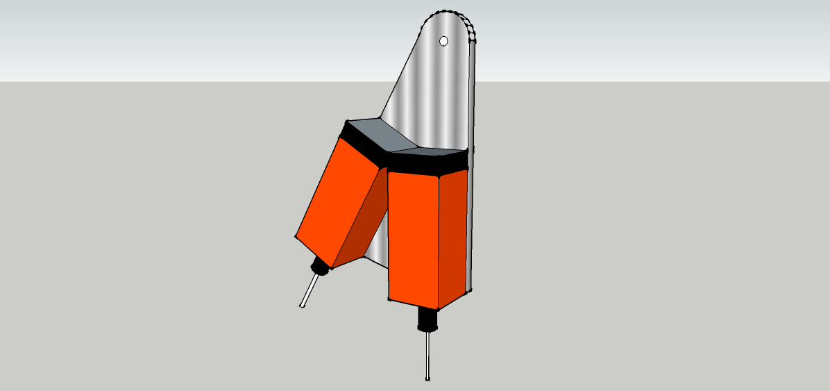
The other side plate supports a swinging plate that holds a pair of angled router motors. These are alternately selected with a push from an air cylinder; the cheapest alternative to a tool changer you’ll ever see.
The tool changer: The top pivot point is in line with each router motor axis so that they both swing into exactly the same position. The pneumatic pusher cylinder is mounted inside the slide box and pushes a peg that goes through a slot – neat huh? Between the motors a round steel plug is pressed into the plate and one of a pair of electromagnets pulls this to lock the plates together (better solutions in comments please).
So there we have a heavy duty industrial quality router with 2 tools and 2 drills; about £20,000 worth if you had to buy one. One could earn a comfortable living with one of these. Not a lightweight project but still DIYable. Don’t get bogged down with cutting, welding and drilling heavy frames; the steel suppliers have all that kit and will make your frame in no time. Just send off your drawings and wait for your cnc router to arrive.
Levelling the beam: There must be a few ways to do this other than sending it away for precision grinding.
A small steel block with a laser on it will show a dot moving up and down a target to reveal the bumps which will respond to a light touch of an engineers scraper.
When the beam is true adding hardened steel guide bars will provide the perfect flat finish.
Panels: Professional machines come with expensive steel panels. As the central box chassis needs to be stiff and straight use MDF panels bolted to the steel to make it neat and strong too. Hammerite paint on MDF is remarkably durable and will keep it all looking very tidy.
Bellows: With a rectangular box sliding on the RSJ there will be no problem in adding bellows to make the machine the ultimate in tidiness and this will be no bad thing for the unlubricated Turcite slides.
For further reading try following http://www.mycncuk.com -a fount of CNC knowledge- and please criticise or add ideas for improvements in comments.

More on this topic in LIST OF POSTS

Advertisement

CNC router – Caterpillar drives

enclosed reduction drive click to enlarge

enclosed reduction drive
click to enlarge

Differential belt drive

Differential belt drive

Driving both sides of a wide gantry present some awkward problems. Coupled long ball screws are expensive and prone to whipping and synchronised stepper motors on each end don’t always step in time and crabbing can occur. The caterpillar drive shown here (top left) for the slide box on the X-axis is intended to enable a timing belt to engage with a rack with the arrangement incorporating a low cost reduction drive.

The X-axis beam is supported by a slide box on each end and each one contains the caterpillar drive (top right). A single drive shaft, with a pulley on each end, pulls the slide boxes up and down the Y axis via long timing belts. The drive boxes contain reduction drives which finally engage with a rack.  We call them caterpillar drives because the drive belt engages with the rack just like a tractor laying its track on the ground. Note that the pull on the belt is in the same direction that the slide box moves and that there is a differential action with the belt moving much faster.
With a couple more pulleys the main drive belt at the top can be brought down to run under the red drive pulley and just above the lower run. Thus the belt can be made to lie, and slide along a slippery nylon bed rather than flap in the air.

More on this topic in LIST OF POSTS

DIY industrial CNC router

CNC heavy chassis

CNC heavy chassis

Cheap computers and software have brought CNC machining within the realms of DIY.


Some smaller routers are not much more than toys but for a machine that can commercially earn its keep we need some size and the ability to hang more tools.
So here we have something much bigger and heavier without increasing the cost to anything like a professionally made router.
Size: In order to machine round the outside of a standard 8’x4’ sheet we’ll need a long and strong X-axis. A heavy steel RSJ will resist the tendency to sag under the weight of two 4.5kW router motors and two drills. Of course a machine that holds multiple tools is ultra productive but also very expensive; usually that is.

We can get to two router motors and two drills pretty cheaply with the tipping tool changer concept. More details here 

The neat thing about an RSJ is that it is not only cheap but the ‘I’ section enables us to put drive gears and the drive rack neatly inside the web.  more details on drives here:
Torsional rigidity is not a strong point but is easily enhanced by welding a heavy tube inside one of the webs. Steel can pick up vibration so filling the tube with heavy chain and oil will make a cheap but effective damper. You only get really smooth finishes on a machine that is well damped.
Z axis: You could buy an off the shelf Z slide and hang that off the X axis for a conventional and simple layout but the logic of that is debatable. When machining flat boards etc there is very little Z movement so it would be better to put the Z under the table so that the two major movements – X and Y – are as light as possible. The Z frame (the whole bed) is raised like a garage car lift with 4 chassis mounted screw posts rotating to drive ball nuts on the frame. Unlike the continuous chain of the garage hoist a short timing belt for each screw connects to one of a pair of drive spindles which are both driven by a central belt and the stepper motor. This way we get reduced belt stretch and a built in reduction drive. This layout enables a much bigger Z travel – 3D modelers note – and makes a fast and responsive machine with a tidy uncluttered look. Air balancing means there would be no heavy lifting for the Z stepper motor.

This unusual configuration has a lot of advantages. The sketch above doesn’t show the tractor drives or the box slides (one for the tool head and 2 to hold up the X-axis beam) which are described in detail here.
The rear mounted drive shaft drives the two differential caterpillar drives that power the Y-axis.

Panels: MDF – easy to cut, cheap, noise suppressing and remarkably robust when painted with Hammerite.

Snags?
Weight: Chassis needs heavy welding skills and reasonable accuracy.
Z-axis: Quite elaborate 4 pillar lift mechanism with guides.

The advantages.
Size: Scaleable to industrial size. Pictured as 2m x 4m here.
Visibility: Whole work table visible without moving obstructions like gantry legs.
Safety: Work table has no sideways movement. No pinning accidents.
Space saving: No sideways movement of table so roughly half the footprint.
Convenient: Router motors present themselves right to the edge of the table.
Accurate: Very solid construction gives accuracy and good machining finish.
Neat: Hollow beams accommodate wires, lights and control panels.
Responsive: Weight of Z-axis is removed from the X and Y axes.
Large Z-axis: Big range possible – good for carving.
Short Y-axis: Single stepper motor drives both ends of X-axis beam so no crabbing.

…. and isn’t it the neatest CNC router ever?

…. and check out the LIST OF POSTS for more like this

Jumping motorised skateboard

Fast, light and jumpy

Fast, light and jumpy

Many versions of minimalist personal transport exist or have been proposed ranging from motorised skateboards to some excellent rubber tracked machines. To home in the best solution lets pose a question. Say you are a soldier about to leap out of a Hercules to a DZ 10km from your final destination. What would you like to strap on your back to make the mission go well, apart from lots of guns and ammo, hot coffee and a pocket full of Werther’s Originals? Most of the world is populated so there are likely to be some rudimentary roads and a few fields to cross so a folding electric bicycle would be a good start but could we get any better, smaller and lighter? Well there’s a problem; as a vehicle reduces in size from something one sits in to something one stands on the forces of acceleration or braking are trying to spin the rider about his centre of gravity and these can only be mitigated by lowering the C of G or lengthening the wheel base – think dragster – so that the forces are countered by trying to lift the load. This is pushing us towards something akin to a skateboard. Ah! Now there’s a twisty idea. A skateboard with a powered single enlarged rear wheel like the tail of a miniature motorbike. To counteract the back flip that acceleration would cause, the rear wheel pushes down to tip the rider upwards and forwards; a handy feature too when a small jump is required. Motorbike rear ends tend to squat under acceleration so the drive would incorporate an intermediate gear to reverse the torque and additional push would come from the dynamic electric shock absorber. Now a sharp twist of the throttle will result in an upward push from behind as well as a surge forwards.
The front end has 2 rugged 8” wheels that tilt and steer like the latest 3-wheel scooters but with a telescopic steering column that is good for the standing position or sitting when the seat is used.
The 15km range is every bit as good as an electric skate board and this can be extended a few times by a tiny 30cc petrol generator, about the size of the smallest chain saw, that can be clipped on just behind the front wheels.
So there you have it. A long distance 3-wheeler that you can wear like a rucksack, sit on, that can jump logs and ditches and needs minimal skill to ride. Now where’s my parachute?

Tyres: The springy rear end allows for solid rubber tyres all round. The ideal profile would be like an inverted ‘T’ with a raised rim around the circumference to give a smooth and economical ride and the side pieces with robust tread that only comes into play when the tyre sinks in mud or snow.