enclosed reduction drive
click to enlarge
Differential belt drive
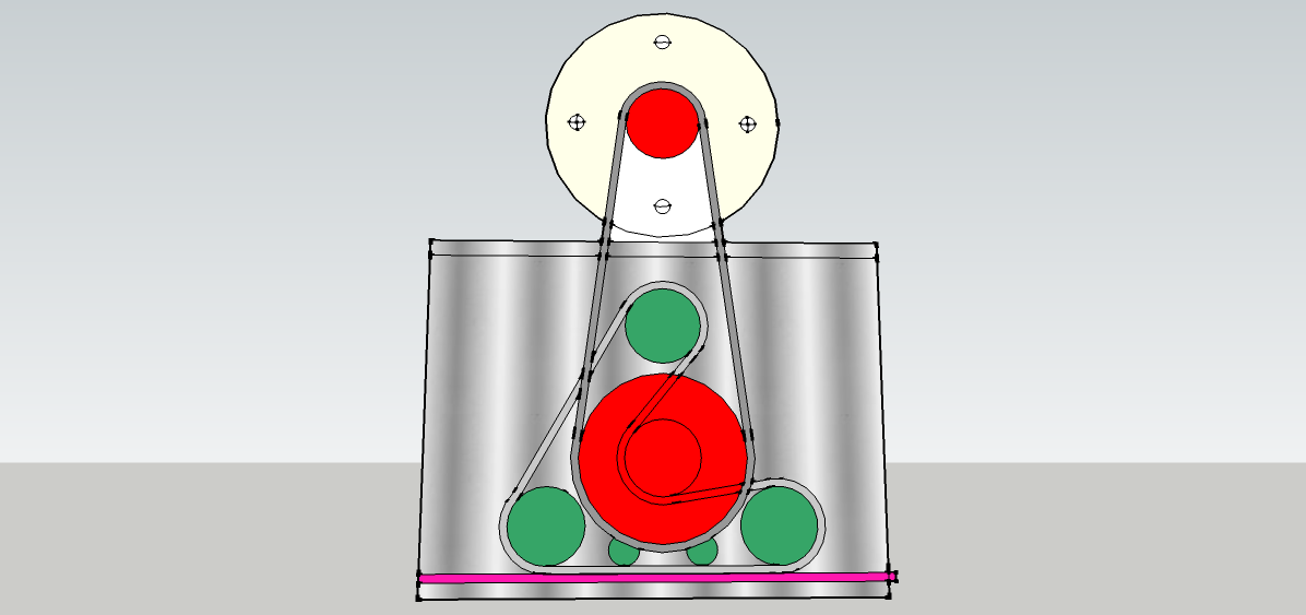
Driving both sides of a wide gantry present some awkward problems. Coupled long ball screws are expensive and prone to whipping and synchronised stepper motors on each end don’t always step in time and crabbing can occur. The caterpillar drive shown here (top left) for the slide box on the X-axis is intended to enable a timing belt to engage with a rack with the arrangement incorporating a low cost reduction drive.
The X-axis beam is supported by a slide box on each end and each one contains the caterpillar drive (top right). A single drive shaft, with a pulley on each end, pulls the slide boxes up and down the Y axis via long timing belts. The drive boxes contain reduction drives which finally engage with a rack. We call them caterpillar drives because the drive belt engages with the rack just like a tractor laying its track on the ground. Note that the pull on the belt is in the same direction that the slide box moves and that there is a differential action with the belt moving much faster.
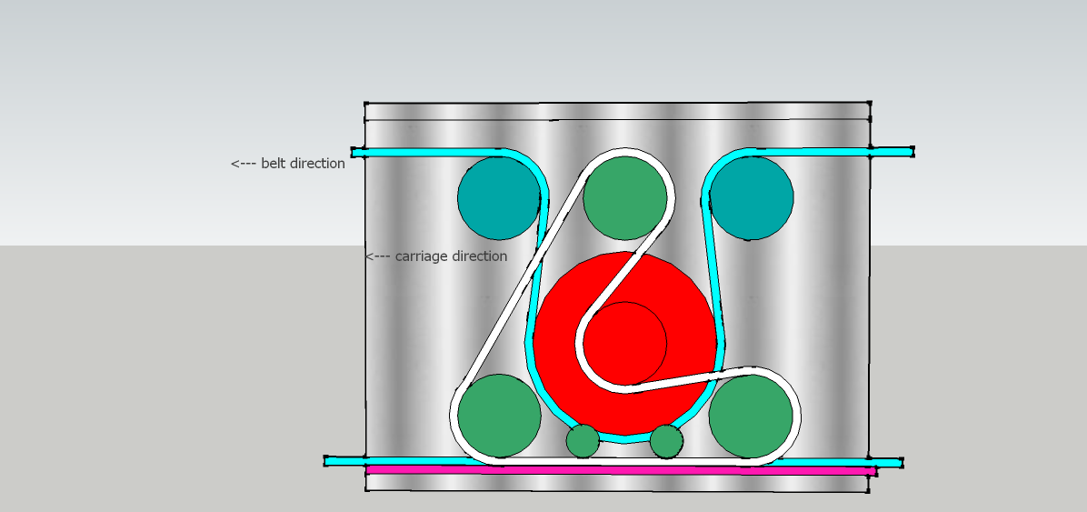
With a couple more pulleys the main drive belt at the top can be brought down to run under the red drive pulley and just above the lower run. Thus the belt can be made to lie, and slide along a slippery nylon bed rather than flap in the air.
More on this topic in LIST OF POSTS
