Ultimate Eco-heating system
Ecological heating (Eco-heating)
NOTE: Dec 2019 This design will still suit many configurations but much cheaper PV panels have changed the rules somewhat. Suggestions for an update, and a simpler diagram, are here at the 2020 revision
Also the RHI incentives have all changed so by all means have a look below but the 2020 revision is more up to date. You can use heat pumps to give unbelievably cheap heating; it’s not conventional though. All the tweaks on absolute ultimate heating system
The Eco-heating goal is simple. To use free or green energy (solar/wood) so effectively that expensive fossil fuels, energy bills and the carbon footprint disappear. The only reason to be attached to the grid is to supply it; well not quite, we might need the grid to smooth any fluctuations but we certainly don’t need much of it or, even better, none of it.
Modern houses are well insulated and need a lot less energy to run than before and a few technological advances have made Eco-heating absolutely viable. PV panels are more powerful – only 3 needed to make 1kWp now.
As a starting point, a tank of water – a heat store – is required to integrate various heat sources and demands. A single heat store makes an excellent heating system but two tanks are altogether much better, especially when it comes to integrating solar and a heat pump. So much more is easily optimised with twin tanks that this is the future for eco- heating systems.
Before you start to plan your own ultimate heating system there are a few points to consider:-
Photovoltaic panels (PV) rarely produce their rated output.
On a bad day they produce only around a third of their rated output – say 100W per panel.
Background electrical demand (fridge, computers, lights, TV etc.) can often be as high as 1kW
The PV panel array will have to be much bigger than the usual 4kWp (12 panels) for there to be enough surplus power to make an eco-house.
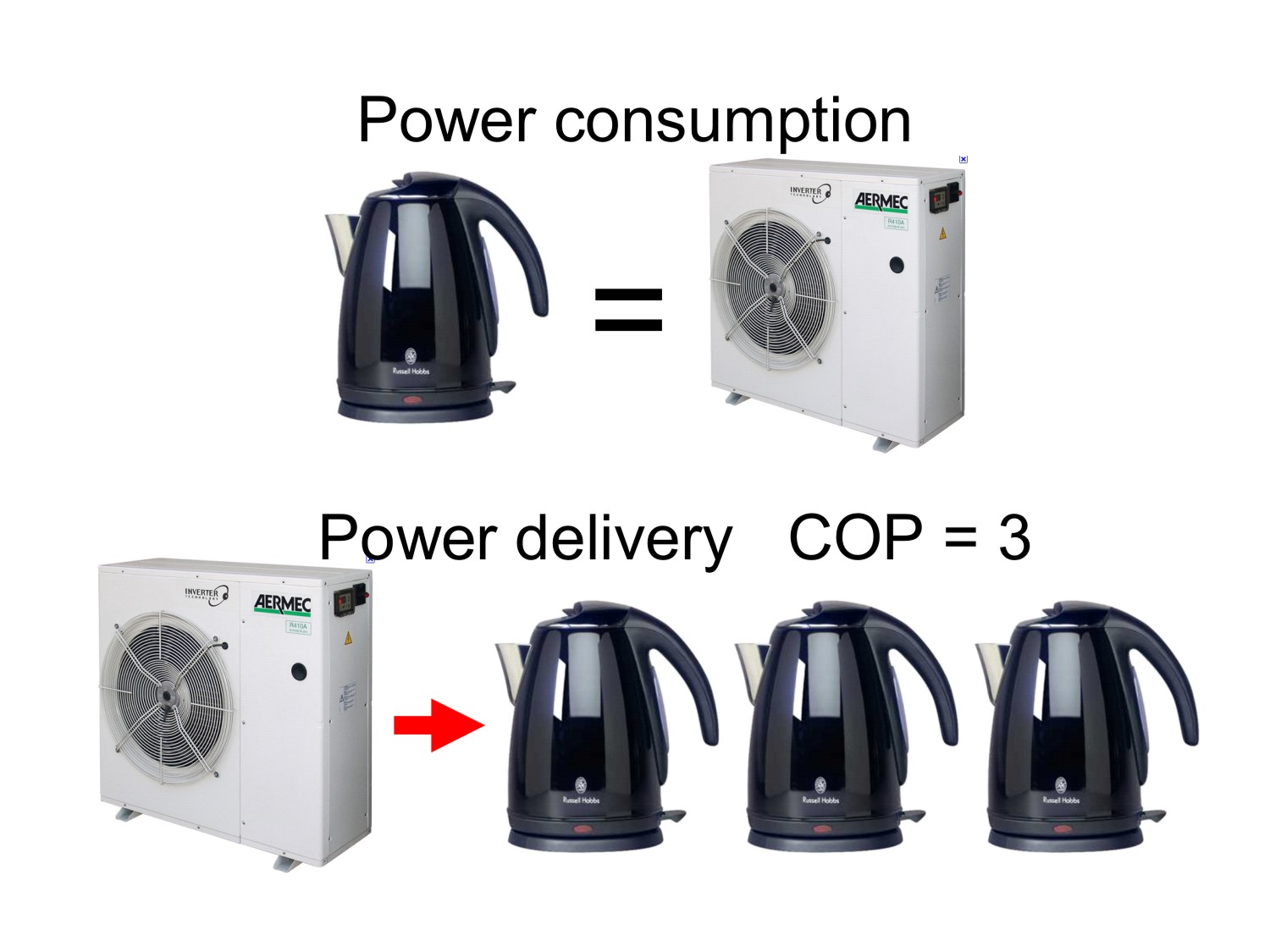
A heat pump takes electrical power and delivers around 3 times as much more energy in the form of hot water. This engineering miracle might be the core of the system, but …
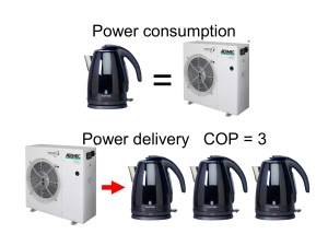
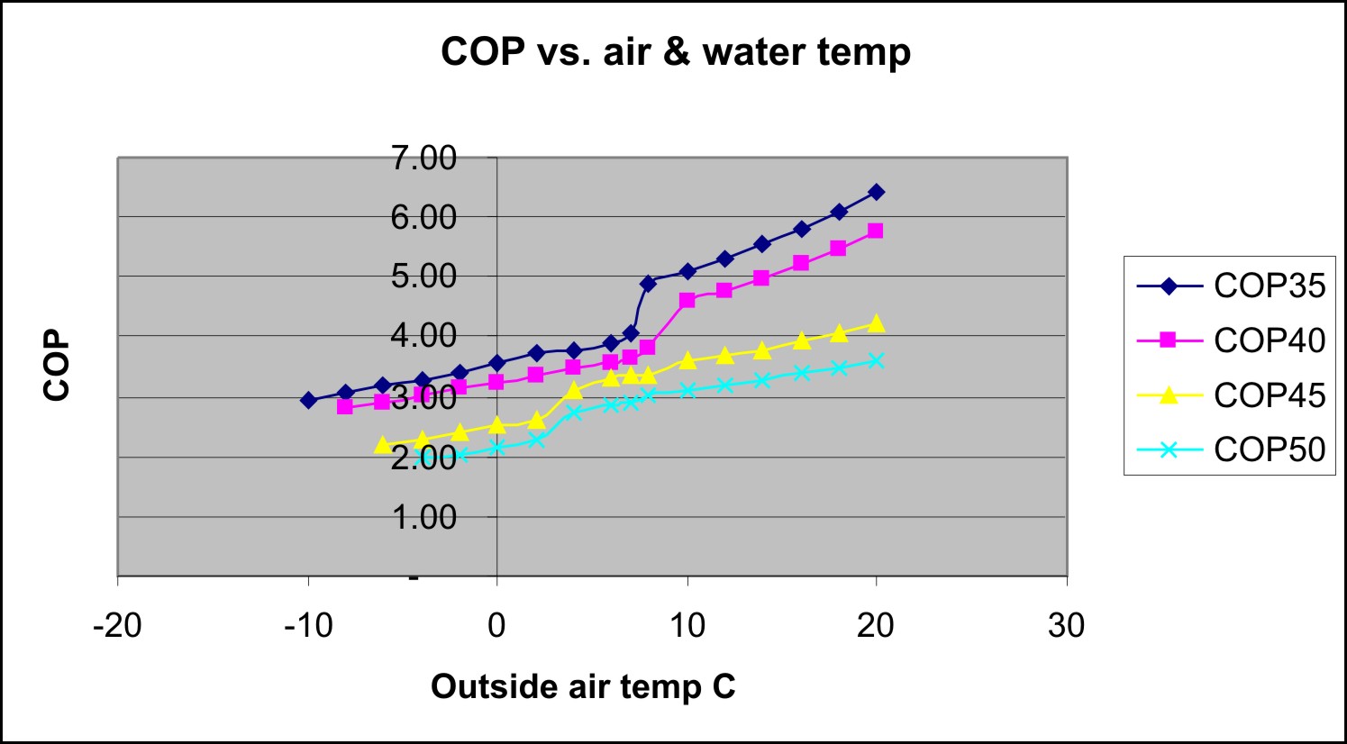
The power multiplier
…. the times 3 trick (coefficient of performance or COP) is highly variable, and depending on outside temperatures and delivery temperatures, can vary from 2 to 5. The manufacturer’s quoted COP is for very specific conditions which you might not see very often. Even the quoted power output of a heat pump will not be reached when it is very cold outside.
Air source heat pumps are a better choice than ground source heat pumps
They cost less and are easier to install. For the full argument see:-
https://originaltwist.com/2015/02/27/air-source-heat-pumps-and-the-renewable-heat-incentive/
https://originaltwist.com/2014/03/19/heat-pumps-in-southern-europe-air-or-ground/
Unfortunately the RHI payments are biased heavily towards ground source which will skew the decision. Even the government is confused about efficiency and we can punish their oversight with the Original Twist Hybrid Heat Pump … four tanks now – how exciting.
PV + heat pump = Free heating
A heat pump on a COP of 3 redresses the shortcomings of the PV panels on that bad day, so a PV and heat pump combination can deliver 300W for each panel and two or three times as much on good days. This energy, in the form of hot water, can be delivered to underfloor heating which usually uses about 50W per square metre of floor and never more than 100W (which would make your feet hot). So, for a rule of thumb, 8 PV panels will do 50 square metres of heated floor area. Then add up to another 10 panels to cover background consumption.
Two things to take on board at this point.
1/.If you are going off-grid your energy storage (in batteries and the water tanks) will tide you over for the bad days and the wood burning stove will always cover all the heating and domestic hot water demands.
2/. A popular size (and so a cheaper size) of PV rig is based around 6kW and this implies a matching 18 panels. Have a look at the overclock and tilt theme here to see why you’ll increase that by up to 24 panels.
Therefore, most self-supporting Eco-houses are likely to have 20 – 24 PV panels on the roof; a lot. The calculation for a Passivhaus is scaled back considerably; there might be no floor heating at all and just fan-coil units , even so there will still be a lot of panels to cope with the bad days.
Air source heat pumps run much more efficiently during the day when the air is warmer.
Not only more efficiently but combined with PV panels much of the daytime energy produced is free. Obviously big PV and a slightly oversized heat pump can produce excess energy which could keep the heating on after the sun goes down. The surplus energy will need to be stored in tanks of water – big ones.
A house with high thermal mass will also work better in this respect.
Solar thermal panels can be made to run more efficiently.
Solar panels can only heat a tank that is cooler than they are. In winter when the tank is usually already hot and solar is weak the panels often stop working altogether. Given 2 tanks however – one hot and one cool – the panels will run almost daily throughout the year and this dramatically improves effective panel efficiency. The Original Twist solar stripper circuit decides which tank, or both together, can use the available heat more favourably.
A pair of 500 litre tanks are only 2m high and together under 1.5m wide. Tanks up to 500 litres can be made of light gauge steel so they are relatively cheap and easy to handle. However there is a case for making the cooler tank 1,000 litres – it’s a cheaper energy store than batteries.
Gas boilers – not quite redundant for big houses
On the coldest night the heat pump with reduced power output and the lowest COP might be struggling, especially if it was sized within the limitations of single phase electricity. A gas boiler is a towering powerhouse by comparison, producing instant high grade heat at a low(ish) price. Hot water recovery times are just minutes and a shower could run hot forever if required. For a larger eco-house, a gas boiler for very occasional use makes sense and ensures that there are no compromises to comfort whatsoever.
Under floor heating is not always best.
Bedrooms need to be heated quickly, usually briefly, and preferably not with a hot floor under the bed. Floors of upstairs bedrooms are often reasonably warm already because they are above rooms which are heated all day so paying to heat them more makes little sense. The answer for bedrooms is the fan-coil unit which is essentially a hot water powered fan heater. Not only will they heat the room in minutes, but connected to a suitable heat pump they will cool it as well. Air quality can be enhanced by UV purification, a boon to asthma and hay fever sufferers.
Towel rails are different.
After your shower the towel rails will need to be on long after you have got up or gone to bed. The timing and heating requirements for towel rails is completely at odds with the rest of the system and they need to be properly integrated with a dedicated pump and timer.
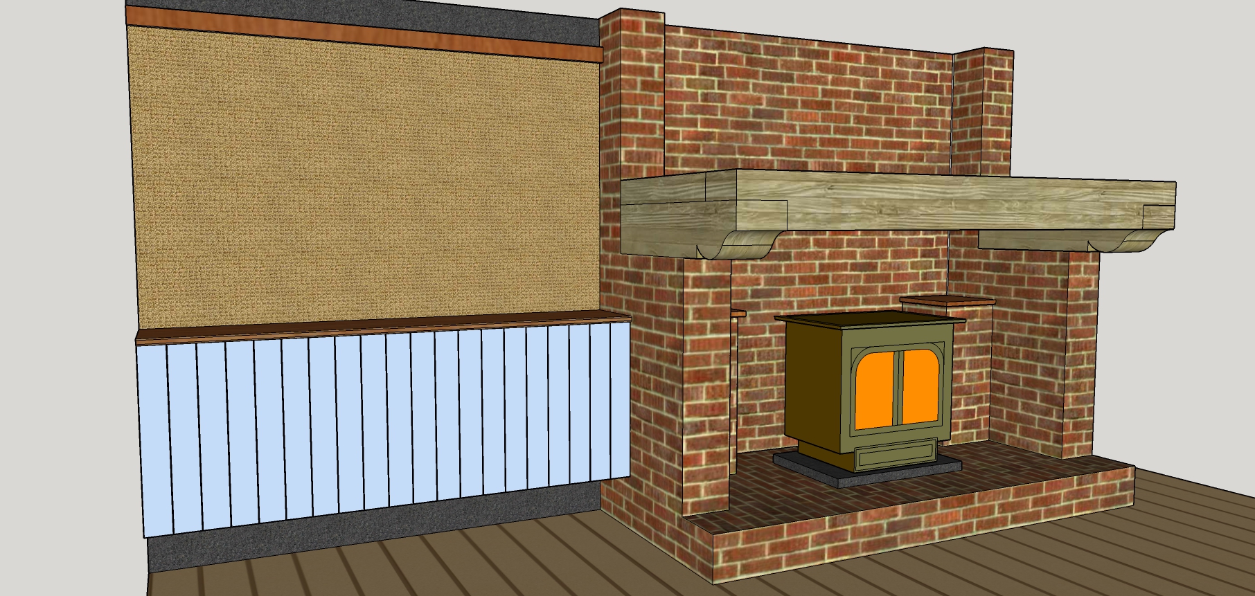
Wood burning stove
Mankind has been sitting round fires for thousands of years; for many people it is unthinkable not to have a real fire in the home. We are talking eco-heating here so an open fire is out of the question but a good stove is much nicer to live with anyway. A big stove with a big view of the flames will be too hot for most rooms so it will need to be connected to the water tanks in order to take some heat away. That’s no bad thing as high grade hot water is not so readily produced by the heat pump. A well matched stove can usually cope with all the hot water and heating needs which relegates the heat pump to an auxiliary role and certainly means that smaller heat pumps can be used.
Controls
Although it is not an absolute requirement, the eco-heating system will work much better with a home automation system such as the Z-Wave Vera. The hot water circulation system, for example, can be activated by sensors in the bathrooms when they turn on the lights. Temperature sensors and relays to activate pumps and valves can be found in the Qubino Z-Wave flush relay which has a built in temperature sensor. The destratification routine (see below) can be triggered by the integrated temperature sensor and the short pump runs monitored by a controller which easily copes with ‘if this then that’ situations.
Efficiency – the humbug
Just a reminder; the sun is free. There is no need to agonise over panel efficiency. Flat plate thermal panels are cheap and reliable so if you need more power just add more. Anyway, during the hotter months they are more efficient than evacuated tube types.
To store daytime heat pump production, the target temperature needs to be raised and that is less efficient than driving the under-floor heating directly. Again the pump is usually running free, courtesy of the sun, so the efficiency doesn’t matter.
Aircon and the renewable heat incentive
The RHI only applies to heating only heat pumps. If you want aircon you should add a separate chiller unit. The diagram above will only be a little different.
The Eco-heating system
Considering all of the above your ultimate Eco-heating system should be like this:-
Much of the suitable roof surfaces will be covered in PV and thermal solar panels.
An air source heat pump
Air conditioning via heat pump
Under floor heating on the ground level
Fan-coils in bedrooms
Fan-coils in some living rooms for air conditioning
A gas boiler (optional)
A twin tank heat store system. 1000 litres + 500 litres.
A wood burning stove connected to the tanks
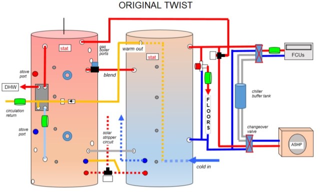
A system that can optimally integrate all of the above with no compromises at all is a tall order. Here it is though; the Original Twist Eco-heating System.
Two tanks it is then – one hot one cooler – but with some sound thinking around the connections to the heat sources:-
Domestic hot water delivery.
Fresh and pressurised water is heated by the hot tank via a plate heat exchanger – standard heat store practice. However, as the hot tank water will be rather modestly heated by the heat pump, the ability of the plate heat exchanger to cope with icy fresh water can be compromised. So to warm the incoming water it first runs through an internal coil in the cooler tank before getting to the external heat exchanger on the hot tank. The pre-warming is not mission critical so there are no controls or pumps to worry about. It’s just a passive coil in the cooler tank.
Back on the hot tank the usual temperature limiting valve – anti scalding – has been dropped in favour of electronic regulation of the heat exchanger flow pump with a Steca TF A603 MC+ controller. This modulates the pump to give a precise output temperature and so leaves more water at the top of the tank ready for more showers. The flow out of the heat exchanger and to the bottom of the tank is also cooler which aids cooling of the solar coil.
Water circulation around the house is essential to save water wastage and eliminate that annoying wait for hot water. The same Steca controller also regulates the circulation pump speed.
Preheating the domestic hot water via the cool tank not only makes a heat pump a feasible hot water maker but it also raises the efficiency in a subtle way. The water in the cool tank is heated just enough to supply the floors and fan-coil units and a heat pump does that very efficiently. Blending this cheaper energy into the hot tank system gives an efficiency boost and also allows the hot tank to be maintained a little cooler which gives another efficiency boost.
Other potential heat inputs to the hot tank (wood, solar and gas) are not disruptive to stratification so hot water drawn from the top is always ready for service.
The solar stripper circuit.
Solar thermal panels connected to a hot tank which is already hot – as it would be with a stove or heat pump keeping it ready for hot water delivery – will be effectively switched off in weak sunlight. But given access to a cool tank they will leap into action at the first glimmer of sunshine, practically every day of the year. Low temperature solar flow addresses the coil in the cool tank first but as soon as it is hot enough it is switched to the hot tank. The flow emerging from the hot tank is usually still very hot so the return flow to the panels goes back via the coil in the cool tank to strip out some more energy. The panels not only run throughout the year but more efficiently due to a cooler return feed.
The Original Twist Solar Stripper Circuit achieves all this with a special 3 port Coster valve that does not interrupt flow as it changes over. The solar pump is started by the cold tank sensor and everything is managed by the Steca TR 603 solar controller which also modulates the pump speed to keep flow temperatures up.
With two solar coils in use, a bigger solar array can be used without resorting to the absurd remedy of using an external plate heat exchanger and circulation pump. Absurd? Imagine sunrise, the panels and the pump start up, the tank is destratified and your morning shower is there no longer. Dooh!
Heat management
With high grade heat sources connected – wood burning stove and solar – the hot tank can get very hot. High grade heat is valuable so the system hangs on to it as long as possible but excess energy will have to be moved eventually. The system does this in 4 stages, each triggered by a cascade of temperature levels.
Destratification – First the pump for the hot water plate heat exchanger is activated for short bursts. This moves hot water down the tank and effectively increases its capacity. The process is limited to the maximum return temperature a wood burning stove can tolerate before the back boiler starts to kettle.
Blending the tanks – If surplus energy is still arriving, a valve connecting the hot and cool tanks opens and the cool tank starts to warm up via a thermosiphon. In this way a wood burning stove would provide for masses of hot water first and then go on to address the central heating. The valve sets to open in a power cut and is controlled by the overheat stat on the hot tank.
Overheat thermostat 2 – In the unlikely event of the cool tank reaching 70 degrees, the overheat thermostat starts the heating pump to dump heat to the heating system or a purpose heat-dump fan-coil.
Power free heat dump – As a last resort, and in the case of a power cut, a power free valve in the hot tank is activated to flow cold mains water through a small coil and send energy down the drain. It is hard to envisage a system where this would really be required but the option is there.
Heat pump integration
The floors pump and the fan-coils pump first draw water from the tank, the repository for free energy. The heat pump starts when the tank temperature becomes too low and then the flow goes directly to the floors or fan-coils. The latter can only be achieved if the heat pump circulation pump flows slightly more than the demand pumps and there are a couple of ways to ensure that. When the heat pump is running under PV energy during the day it will top up the tanks or supply heating depending on demand. Heat pump set points to suit fan-coils or floors will be triggered by the relevant circulation pumps and by the PV output.
Controls
You might imagine that a sophisticated control system would be needed but that is far from the case as many of the functions are independent of each other with only temperature levels causing any interaction. For example, the circulation pumps for floors and fan-coils are only activated by programmable thermostats which do not control the heating. The heat pump is timed and only tops up the tanks if temperatures fall enough to call it, otherwise the wood and solar do the job. Destratification and blending are all independently triggered by temperature levels.
Simplicity is a major benefit. Should any problems arise there is no need to call in a specialist expert.
Who makes it?
The system is based on a standard heat store with a few additions and those additions contain nothing new or untested.
Despite the simplicity this is the absolute cutting edge of Eco-heating systems.
Pre-wired and plumbed this is a quick and cost effective way to solve all your heating issues. The successful integration of wood and solar means a smaller and less expensive heat pump can be used with fewer P.V. panels to drive it. Considering all these savings and minimal running costs the Original Twist Eco-heating System is what every new Eco-house needs.
The Original Twist Eco-heating system
Features summary
Stainless steel tanks – should last a lifetime
Total of 1,000 – 1,500 litres for energy storage
One cool tank for virtual stratification.
Mains water pressure is maintained but tanks are unpressurised
No hot water is stored – legionnaire’s avoidance
2 stage hot water heating for heat pump compatibility
130Kw heat exchanger for hot water making – more if required
Hot water circulation
Anti scalding
Suitable for solar input of up to 14kW
Solar stripper circuit for dramatically enhanced panel efficiency
Special large ports for wood burning stove gravity connection
Extra sensor pockets for home automation compatibility
DHW prioritised with energy overspill to heating
Condensing gas boiler optimised – controlled return flow temperature
Heat pump optimised and compatible with other heat sources
Heat pump COP raised through extra daytime running
3kW immersion for backup heating
4 stage safety system for energy control
A mix of under-floor heating, towel rails and fan-coils can be used
Fan-coils and a suitable heat pump can give air conditioning


Leave a comment