Modern canal boat

click to enlarge

click to enlarge

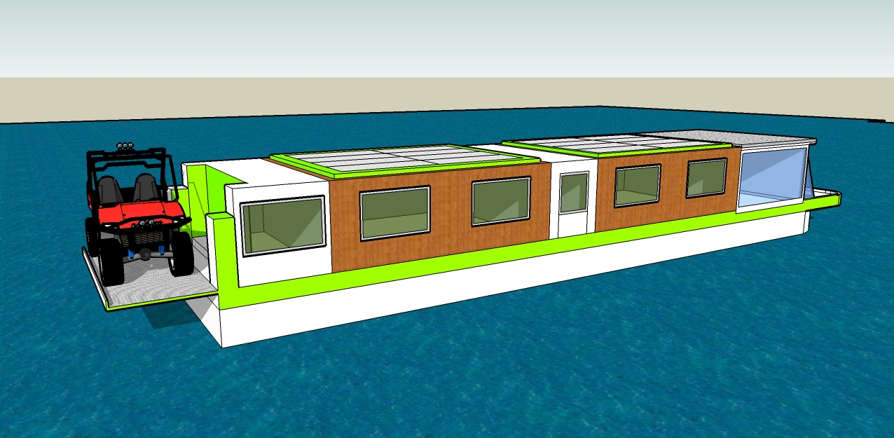
Introducing the Original Twist canal going house boat; in the style of a narrow boat only bigger, better and absolutely modern. As a living unit it presents an economical lifestyle choice. For around £160,000 you get very low cost housing and maybe some change left over for a holiday house, long ski breaks and other good things. A comparable land based house or flat would be twice the price because of the cost of land, a boat on the other hand effectively rents the river via the canal licence and avoids council tax. This one avoids energy bills too which is a good start.

A house boat might be small but as well as reduced outgoings there are some great advantages. You are never stuck anywhere you don’t like; if you need a change you can just cruise to somewhere else, maybe near a cosy riverside pub. River life can be like an aquatic pub crawl but without the driving. You’ll make more friends among the friendly and hospitable canal community too, especially with the most interesting boat on the water.
There is more scope for travel than just the English waters as you can get a tow across the channel to use the huge French network extending all the way down to the South of France where winters are not so harsh. Otherwise the house boat is an attractive proposition for a house swap so the whole world is your lobster.
It’s a tough life being retired!

The Original Twist Eco-house boat is all about, modernity, comfort and enough economy to make a modest pension go far. Many traditional boat ideas have been updated to achieve this.

Construction
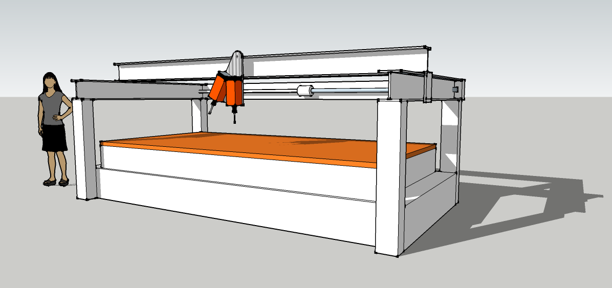
Unlike a go-anywhere narrow boat ours is 10 feet wide and 55 feet long – we’ll forgo visits to a few stretches of narrow canal in exchange for a lot more room and the garage – yes that’s right, a garage.
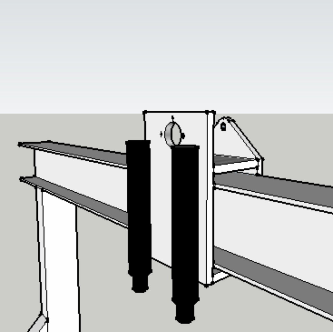
The shell of the boat is normal steel but without the enclosing steel roof parts. The front saloon and the rear transom are full height steel as is the central bulkhead that separates them. The two open parts between the steel constructions are connected at roof level by tubular trellised ladder frames which run the length of the boat interrupted only by the central bulkhead. The open parts of the boat are then covered by 2 insulated wooden rooms made of plywood and foam panels (SIPS).which are factory prefabricated – complete with windows, pipes, wires etc. This makes the boat lighter, cheaper and better insulated.

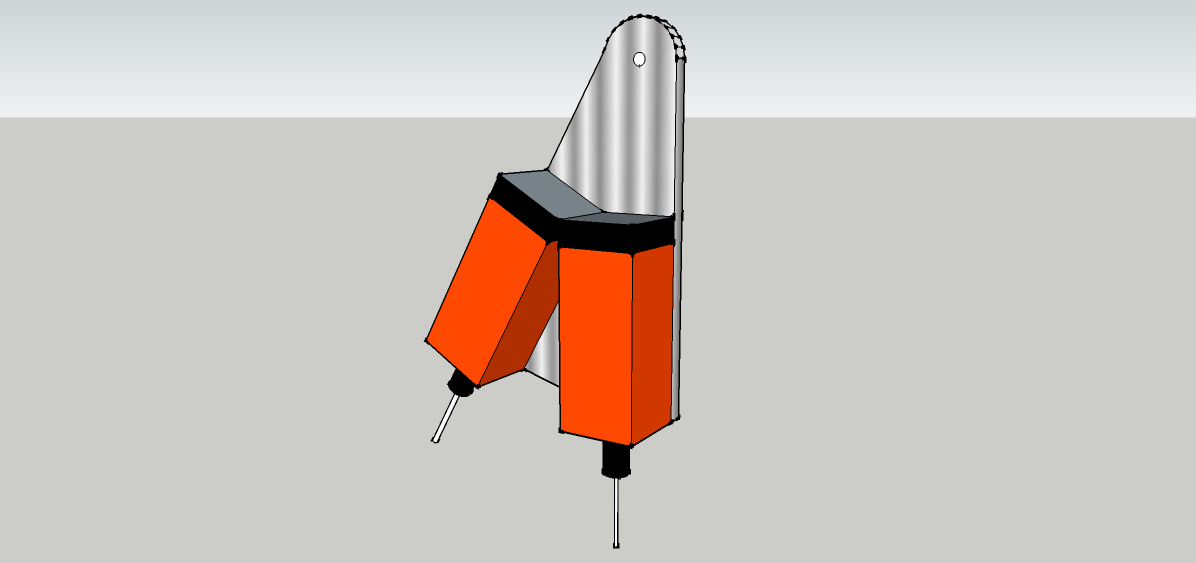
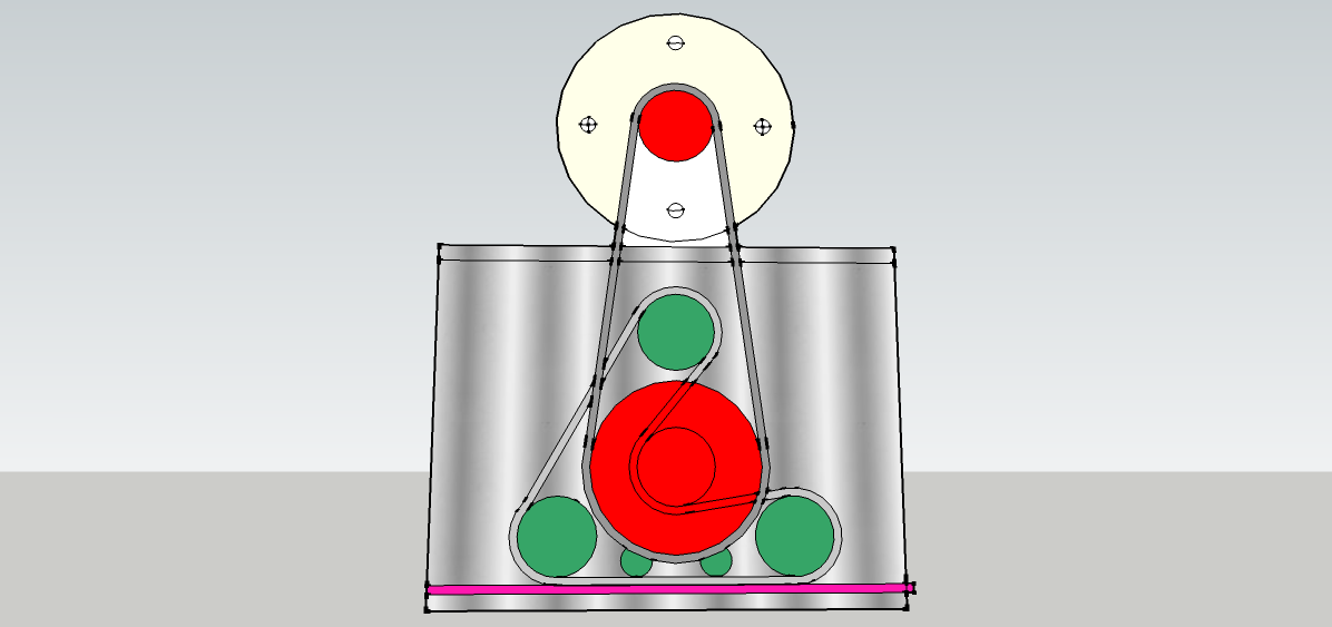
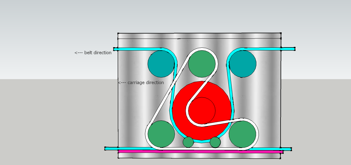
The two central living spaces house the kitchen a bedroom and shower room, all with heated floors. Each has a large pop-up roof (just like on a camper van) to give a more spacious feel while being flattened whenever a low bridge is encountered. These roofs carry the solar panels and can tilt sideways in either direction to catch the sun – the simple mechanism to switch hinge points is activated by the flick of a switch – an air cylinder shoves a cradle from side to side.
The steel and glass front saloon is very light and airy with a door giving access to the front deck. Standard fan-coil units are turned on end to make a pair of powerful demisters for the huge windscreen and to heat the room too.
A flat sun deck on the roof of the saloon makes a great place to watch the world go by and as we shall see later the boat can be steered from up there too.
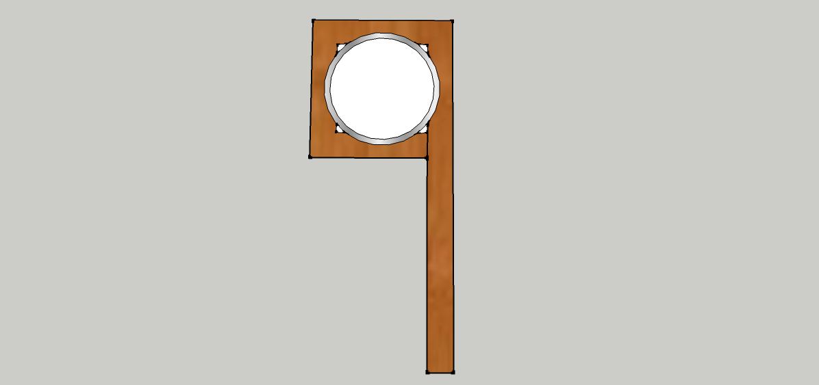
The steel rear transom accommodates the propeller shaft, engine mounts, rudder mechanism, a niche for the air source heat pump.  A tail hoist mounted across the back (like on delivery trucks) supports a light vehicle such as a Polaris RAZR side by side.  After adjusting the height the ramps are dropped and locked onto a nearby bank so one can drive off in style and comfort. What is life without wheels?  Because the hoist can be folded up, the length of the whole boat can be shortened to navigate some of the tighter locks. An awning can be extended over the vehicle and there we have it; the first house boat with a garage.

Eco-tech
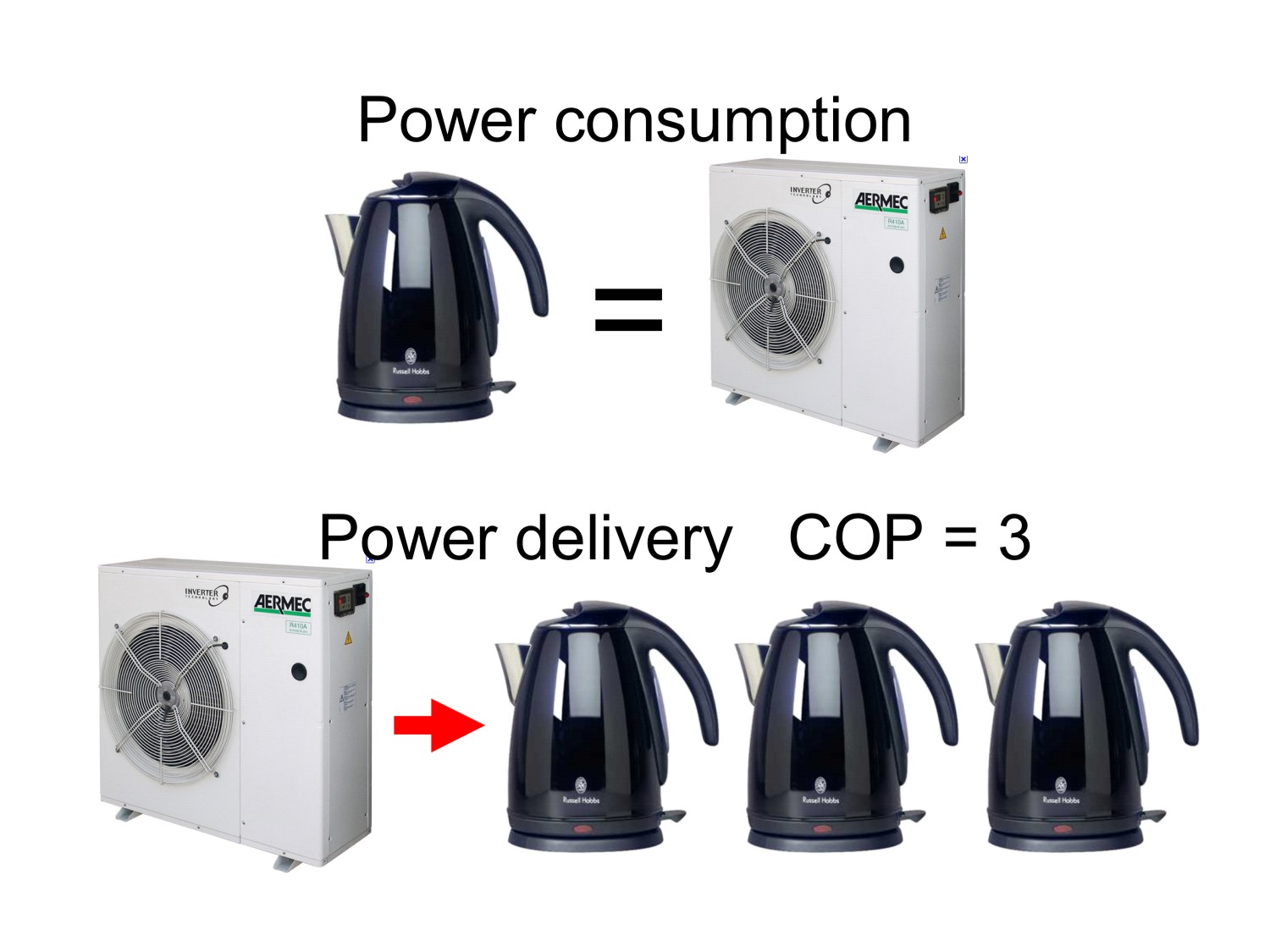
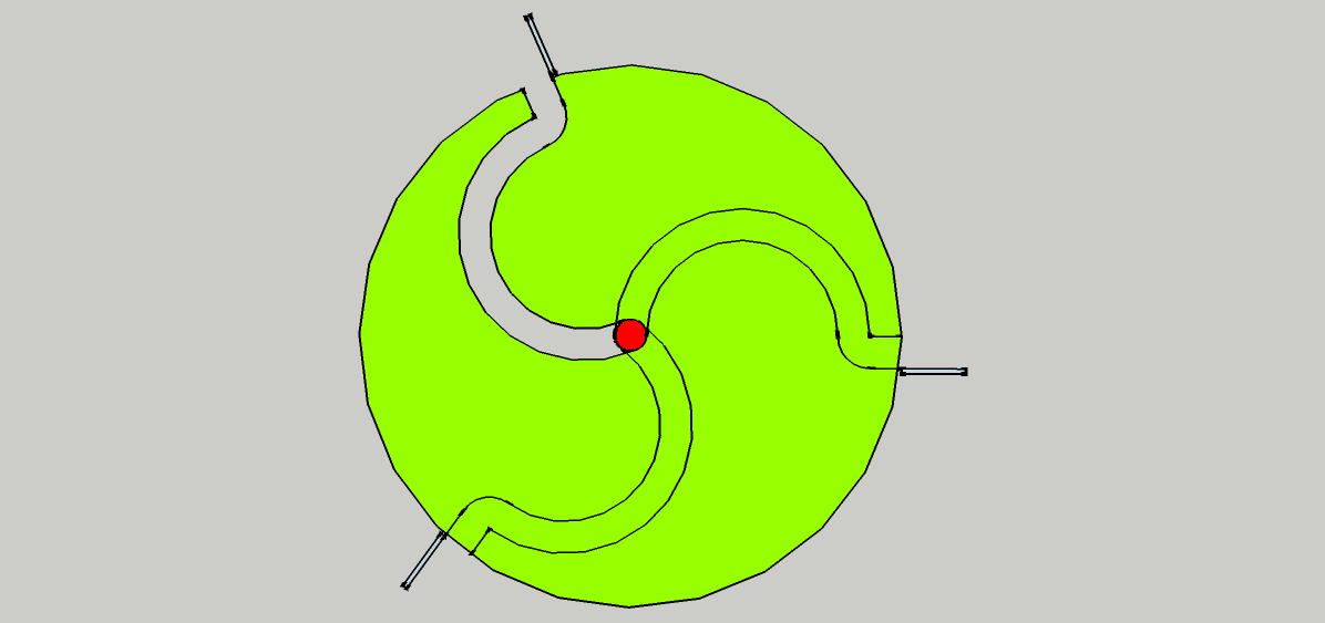
The real point about eco-technomologicalness is to get along as cheaply as possible without damaging the planet. The 20 solar panels on the top produce a nominal 8kWp; a lot more than most domestic arrays and enough for the small air source heat pump and to charge the batteries for the electric hybrid drive system. The hybrid drive is almost identical to that on the Original Twist hybrid 3-wheeler found on this site; here with a Lynch motor and a Kohler water cooled diesel. The usual benefits of a hybrid drive are there; the batteries give a few hours silent cruising and the diesel can take over indefinitely. The batteries are mostly solar charged or sometimes diesel engine charged with the Lynch motor doubling as a generator. Many moorings supply electricity so the batteries can be charged on cloudy days. With the air source heat pump the heating will run cheaply and conveniently off connected electricity or the batteries.  So there are 3 sources of heating power; the PV panels, outside electricity and engine cooling . Most boat engines are cooled by river water but here a second coil in the heat bank uses the 60% of wasted heat to make hot water. There is no connection to the river or the gunk that blocks up the filters (boat owners nod knowingly here).
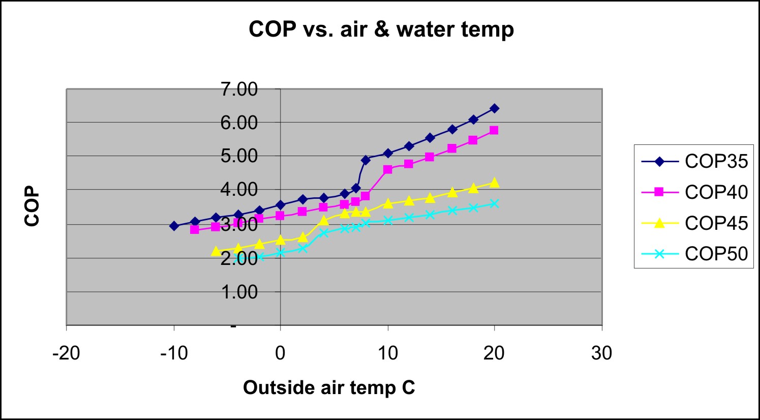
Heating is supplied by the little 2kW heat pump which delivers about 6kW. N.B. River water is not used as the heat source. See ‘Air source heat pumps in Southern Europe’ also on this web site. here
Notable omissions are a wood stove and any gas as there is no need for either. Cooking is all electric.

Controls
Control of all the lights, heating, entertainment and even the steering is done by i-pad and Z-Wave meshed radio modules which are cheap, reliable home automation items. Narrow boats are usually driven from the back, a bit like a bus driver standing on the rear bumper. We can sit at the front in the saloon and steer from there or from anywhere else within range of the wi-fi; perhaps the sun deck even from the nearby pub! The Z-Wave controller allows for plenty of home automation tweaks like lighting control, security and leak detection, all from anywhere in the world. Theoretically the boat can be driven from anywhere there is an internet connection.
Actuators to move things like the roof panels and the rudder are operated by compressed air which is cleaner and easier to maintain than hydraulics. An i-pad and Z-Wave relays makes child’s play of these things; even a simple dimmer switch allows proportional control of the rudder.  The motorised satellite dish also needs to fold into a recess in the centre section when a bridge is encountered.

Neat extras
To make the kitchen a great place for eating while admiring the view the picture window on one side tilts up and out and a table is pushed outwards to make use of the outside space. Once parked up an extending awning over a drop down side deck, complete with an extending Barbie unit, makes an outside cooking area.

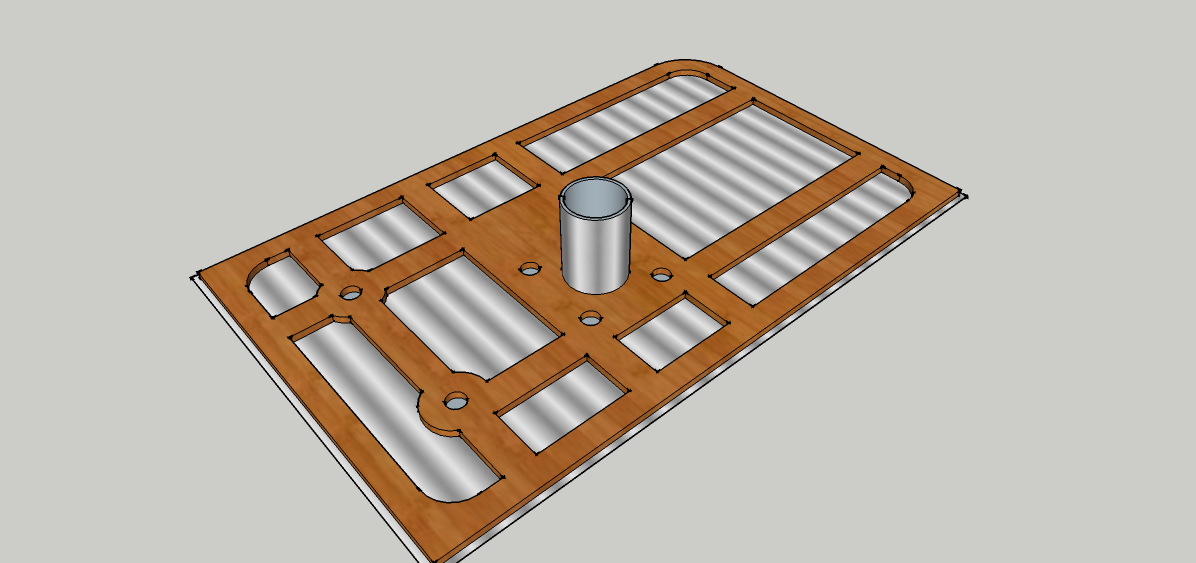
Central dust extraction – The centre section houses a fixed dust extractor plumbed to outlets around the boat to make cleaning much easier.

With a boat like this life will certainly be rich and varied.

ECO-HIPPY – One who is sufficiently off-grid to live almost cost free.

More on this topic in LIST OF POSTS

← Back

Thank you for your response. ✨

Silent PC

Top view

Top view of the case

Fanless PC case by Original Twist

A totally silent Mini ITX PC case made from low-cost, off the shelf components with an easy progression from prototype to large scale production.

Things are moving on in the world of desktop computers; they should be cheaper and simpler, but, would you believe it, they’re not. Why?

Perfectly useable CPUs now run much cooler and use less power so, unless you need a powerful gaming rig, you don’t need big fan cooled power supplies or case fans. Heat pipes can remove all the heat most CPUs make.

Solid state discs (SSDs) are cheap and clip neatly into the motherboard M.2 slot. Hard drives are not required at all when data is stored in the cloud.

So no remote SSD and HDD parts on the drawing and what is left? Just a mini -ITX motherboard and (maybe) an open power supply; two components then.  No moving parts, no noise and much less cost.

The Original Twist fanless PC case

The aluminium extruded fin case side is glued onto extruded aluminium corner sections; both are available from stock.  The corner sections have slots to accept side panels in any material – the blue parts on this drawing could be marble, for example, or wood.

The huge finned extrusion makes one side of the case.  By huge, I mean really huge. 40mm deep and 160mm wide with a 10mm thick base all ready for embedding 6mm heat pipes. Heat transfer is via 6 heat pipes and a copper clamp on the CPU.

There are multiple disc drive mounting options opposite the motherboard and also higher up the case if required.

The open case power supply (PSU) is mounted low down in the side channel extrusion.  Any heat produced from this and the motherboard drives the updraft.  The case is deliberately like a chimney and needs a bit of heat to get going.

Cooling

Side view

Side view

The Magic Power (PSU) in the drawing is only 80W so we’ll probably drop that. A better solution will be a Pico-PSU i.e. an external (sometimes internal) brick with internal ATX distribution leads. The case can easily cool the 65W of the popular Core i5 8400 which will make a very high performance machine at a reasonable price. The 6 heat pipes only use the top half of the case.

When standing up the tall chimney case draws air up through the bottom and expels it at the top so cooling is effected both inside and outside the case. The aluminium corner extrusions are part of the heat sink and are bonded on with heat transfer glue.

The finned  clamp for the heat pipes on the CPU sits neatly in the airflow as do the heat pipes on their path to the side wall. The mother board, mounted at the bottom of the case, heats the air at the lowest point. Full height cock’s-comb RAM coolers also heat the air low down and the same for clip on fins on the SSD.

Case size 124.5 x 240 x 375mm

The components dictate the shape.

Width – the I/O shield between 2 corners

44.5+40+40 = 124.5mm.

Side length – the finned extrusion between 2 corners

160+40+40= 240mm

Height/length – 170mm motherboard with space for HDD above and masses of heat sink

375mm.

Design notes

The corner extrusions come with threaded inserts for the ends and these are used to bolt on the top and bottom plates.

4 big round feet enable the start button to be fitted in the base plate as well as the ‘power on’ LED and an angled power plug.

The radiused corners on the end plates match the case style.

Market position

There are contenders for this silent PC slot but they are generally expensive and don’t have as big a heat sink. They are computers with heat sinks – ours is more a heat sink with a computer attached.

The beautiful, contrasting black and aluminium finish looks truly modern making this ‘the computer you want’ and in every way better than ‘the computer you need’.  Design flexibility allows the non cooling sides to be in various materials such as wood, aluminium or marble, none of which requires special tooling to produce.

Flexibility

This case provides excellent flexibility for product variation and expansion. The side panel with the I/O plate is long enough to mount DVD players or removable drive bays.

Marketing

The philosophy is simple. Cut waste and spend the difference on better components.

This solid aluminium PC brings you beautiful modern looks that reflect the quality and performance of the internals.

To bring you the best value for money with absolute reliability we removed all the moving parts. All discs and fans have been replaced by top quality components to bring you the best value, high performance, totally silent PC.

The solid state drive gives exceptionally fast boot times and application loading.

Super fast USB-3 ports are available for you to plug in your external media storage devices or there is room inside for a hard drive.

The side plate holding the PSU can also house an optical media drive bay (41x146x185mm- dotted line on the drawing).

The Technical stuff  below … read on if that’s your thing

Assembly

heat pipe layoutThe computer is assembled with the finned side down. The heat pipes are cranked down once clear of the motherboard and are pressed into the machined slots in the side. After that the PSU channel and the opposite face plate are fitted along with the I/O plate.

Any SSDs or HDD are screwed onto the lid with their looms running neatly up the side so as not to impede airflow. This lid and attached corners then bolts on and finally the end plates hold it all together.

The bending of the heat pipes is fairly minimal but it is, none the less, quite critical. The sketch above shows how just 3 shapes of bend are needed to fit all six pipes. The yellow positions show where additional heat pipes could be laid to increase the effective heat sink. The pitch of the heat pipe slots on the heat sink have to be exact multiples of the pitch on the CPU block.

Thermal performance calculations

The 6 heat pipes on the CPU block can remove at least 15W each and almost double that with the case in the upright position. Additional air flow through the case in this position will also remove some 10W from the CPU heat sink. So the pipes can remove well over 100W but, of course, we need to dispose of this heat through the case.

The heat pipes only lie in half of the finned side and the manufacturer’s figures suggest a DegC/W of 0.45 for this length. With the CPU at 50C and a room at 22C we would be looking at 65W cooling power which is in line with the 65W Core i5 8400. Actually CPUs can run much hotter and the cooling power would be equally higher.

The heavy aluminium heat sink side has plenty of room for five additional heat pipes to be placed between the existing ones and with heat pipes embedded along its entire length the case would be able to remove around at least 80W.  It is hoped that the case will be able to lie flat for 55W chips and be good for practically anything while standing up or on a VESA mount. The added cooling power of the corner extrusions has not been taken into account in these calculations so real world performance should be much better than indicated.

Theory is all very well but we can be sure by comparing with several existing silent PCs which work perfectly well. The Original Twist design has cooling surfaces of around 5 times that of the others so this should be the best of its kind. Some PCs have heat sinks; this PC is a heat sink!

This case is not in production yet. If you would like to own this design and the business of producing it please get in touch using the Original Twist contact form.

← Back

Thank you for your response. ✨

Magic disappearing table

Now you see me

Now you see me

Now you don't

Now you don’t

You’ve been one of eight guests for dinner in a very modern eco-house. You all dined on a lovely heavy wooden table standing on four polished steel pillars; all very much in keeping with the modern house. You help to clear away the last plate into the kitchen and when you return 10 seconds later the table has completely disappeared. What? Your hosts were in the kitchen too so where has it gone?
OK, here’s the secret of the Original Twist magic table, and strangely, to make one table disappear you need 2 tables. Every conjuring trick needs a secret prop.
To start with imagine the original floor – for me, wide lime-washed oak boards – and this is where the table starts off; at this moment it is the floor. Underneath there is a small pit just big enough to accommodate the 4 steel pillars the bases of which screw into a rectangular frame which is raised and lowered by screw jacks and an electric motor. To go techie for a moment, there is an upper frame too with big DU bushes in blocks to steady the legs. When the floor/table is raised up you don’t see a hole in the floor because immediately under the first table there is a second identical floor section with 4 holes through which the legs move. When the legs base frame comes up to the top of the pit it pushes the second floor up to exactly the right height and the illusion is complete. The table has appeared from nowhere and the floor is exactly like it was before.
Hygiene would be an issue but with a rubber backed rug over the floor the table will never have been walked on and double protection would be afforded by a tablecloth as well.
Servicing can all be done from above and would be even easier done from below if the pit had a side hatch accessed from the floor below.
There is more to this concept that the sheer theatre of it. The easy removal of a substantial table makes grand entertaining in a downsized house all very possible without having that old hat idea of a largely unused dining room.
There is a business waiting to be started here. Precast pit and frames etc waiting to be fitted to the floor. If you are interested please contact me on the form below.

More on this topic in LIST OF POSTS

← Back

Thank you for your response. ✨

Air Source Heat Pumps vs. gas boilers

First the bad news for heat pumps. The Energy Saving Trust heat pump survey in 2009 found that many users were not impressed at all. The follow up in 2013 improved the results but the final average system COPs of 2.45 (air source) and 2.82 (ground source) were still way below the headline figures quoted for these machines a lot of which are claiming over 4 these days. So maybe heat pumps are intrinsically good but tricky to install?


Despite all that, what is really good about heat pumps is that they can deliver more energy than they consume in electricity.

The power multiplier

So a small one would be just like this; working on the power of an electric kettle but delivering the power of 3 to your hot tank – a COP (Coefficient Of Performance) of 3 then. By contrast your immersion heater delivers and also consumes the power of an electric kettle so it has a COP of 1.

Heat pumps are all sold with an industry standardised COP. This is misleading to say the least and the reason why optimism is defeated by experience. Far from being a fixed figure the COP actually swings widely depending on outside air temperature and temperature delivered in the home. The COP plots here show how a kick is engineered to give a good headline figure; that kink in the graph is exactly at the publication point.

A sneaky kink
A sneaky kink

You might buy a machine with a quoted COP of say 3.75 but while making domestic hot water on a cold night it will be working at less than 2. There are benign swings however and given a sunny winter day with some warm air to chew on an ASHP can see COPs almost up to 5. You can see this on the dark blue line on the graph. Delivering 35c water to the underfloor heating the COP goes over 5 as the outside air goes over 10c. Note that the pale blue line (delivery temperature 50c for radiators) still only goes to around 3 so for most of the time the average COP will only be near 2.5. So, heat pump with radiators – think carefully.

Gas per kW.hr costs about a third of electrical power so after adjusting for efficiency a gas boiler is similar to a heat pump with a COP of 3. Many people in the survey would be comparing their new heat pump to a gas boiler; a formidable opponent when running on cheap gas. A gas boiler is much more powerful than most heat pumps and delivers at usefully high temperatures so a heat pump must have an overall COP of over 3 to justify a hefty purchase price.
Perhaps the performance could be lifted further?

The next bit is a bit dull – you might want to skip on to conclusions below.

To winkle out some ideas we’ll take daily temperature data for January in Guildford (http://www.wunderground.com/) and relate that to a COP matrix made from the published data from a modern ASHP (inverter drive scroll, r410a, delivering to under floor heating at 35 degrees).
We will be looking to lift the COP by running the ASHP at the warmest ambient temperatures possible.
A look at a January temperature trace shows:
There is usually a 5 degree swing between the mean night time temperatures and the daytime mean.
Night time temperatures are flatter and longer than the sharper daytime peak at 1-2pm.
The morning transition from lows to highs is halfway there by 10am.
Temperature rises coincide with sunrise, not surprisingly.

Relating the above to the COP matrix:
Running a 7hr shift from 10am gives an average COP of 3.86 – much better than gas.
The equivalent night time shift only gives a COP of 2.92 – but almost as good as gas.
If the pump has to make hotter water for radiators these day/night figures drop to 2.7 and 2.11 and for 55 degree hot water making 2.3 and 1.85– gas beats this hands down.
Storing daytime running means that delivery temperatures probably need to be around 50 degrees leading to an average COP of under 3 although bigger storage tanks improve this.
ASHPs can be smaller if they run continuously day and night on an average COP of 3.4 – still 13% better than gas.
Direct electrical heating is often used to boost hot water making (COP = 1) and this can lower the average COP. If we can avoid this practice and run predominantly in the daytime it should theoretically be possible to get a COP of 3.35 (7hrs day, 2hrs night, 2hrs hot water).

Transmission: Put 100W/square metre through your floors and your feet will be uncomfortably hot so somewhere near half that will be a good yardstick for calculating the power you need.

Conclusions
A small ASHP can run a bit more efficiently than a gas boiler in a modest well insulated house. Fan-coil units in bedrooms and underfloor heating elsewhere are essential. The heat pump should run in daylight except maybe for a boost before dawn to guarantee morning showers and take the chill off the floors.

Of course, with PV solar panel prices falling relative to electricity prices, the time is coming when your heat pump will run for free while the sun shines. At the moment it looks like we are firmly in no brainer territory and it is certainly worth checking now to see how the sums stack up.

A tip to make your heat pump installation cheaper. Use the PV panels and an energy diverter (e.g. Eddi) to heat your existing immersion heater. then you won’t need the special tank to accompany the heat pump which will just do central heating. Your installation might get a lot nearer to the £5,000 grant.

And while we are at it, don’t forget to consider a mini-split heat pump air conditioner; It’s an air to air unit that makes heat as well as cooling. They are relatively so cheap it’s hard not to go and get one right away. I did, bought and installed for under £1,000.

so, probably nothing conclusive so far. Have a look at ‘off-peak energy storage’ and you’ll instantly become a heat pump convert.

More on this topic in LIST OF POSTS

Ukraine Drone Warfare

Quadcopter/puck ready for launching

Quadcopter launcher

Quadcopter launcher

This idea was first published here in 2015. A pity there has been no interest. Remember that long Russian convoy menacing Kviv? What if a few hundred drones had blown the tyres off those vehicles and any supply vehicles?
The Original Twist concept looks like a fat Frisbee or puck, at least it does for the first few hundred metres of flight with not an arm or propeller in sight.
Transportation: The propellers and arms are all tucked safely out of harm’s way, folded into the base of the puck. The folded puck can then be handled roughly and easily stacked up in racks.
Launching: Here lies the real Original Twist. As you will see in the launcher description below, the robust pucks can be flicked out like clay pigeons at the astonishing rate of 600 a minute. There is no battery power used for taking off, getting under way and reaching height which adds to their range. Neither is there a warning howl as hundreds of drones start up, just a line of discs silently darting across the sky to a location away from the launch site and therefore no giveaway of the origin. At the end of the launch trajectory the propeller arms flip out and the journey towards the enemy continues using onboard GPS. The propellers sit at a slight angle to the body so that when in flight the puck is perfectly aligned to the airflow. Reduced drag with some lift from the domed top allows a good range of at least 12 miles which allows one launch vehicle to cover an area of over 400 square miles.
Attack: The quadcopter/puck bodywork is made of moulded plastic explosive so they are very much like intelligent flying bombs. They can, for example, fly to a given location and using infra-red cameras locate human sized heat signatures for immediate targeting; no sniper will be safe from being blown out of his hiding place. Pucks can communicate with each other and with the host computer using a meshed network where signals are passed down the line. Other pucks can be programmed to cluster into a much larger bomb before simultaneously exploding. Pre programmed pucks will be immune to radio jamming and execute their missions come what may.
Tactical use: The near silent deployment can have a myriad of other uses. Surveillance from on high or with sound and vision lying on the ground, simulated radio transmission sources to attract enemy fire, diversionary attacks from various directions and overhead flares to light up the enemy. They can even provide ‘Shoot me’ targeting information to overhead drones and airborne weaponry.
What could be more demoralising to the enemy than intermittent attacks from the air at no significant cost or risk to the other side? The biggest fear will be a ‘Cluster puck’ attack where several successive droves are launched and are resting on the ground nearby in preparation for a massive orchestrated attack.
A set of pucks with an affinity for vehicle wheels could be launched and without any difficulty a whole convoy of vehicles could be stopped in its tracks, or what’s left of them!
A major comfort to troops in hostile territory will be escorted manoeuvres. Protection from ambush is provided by pucks flying apparently random recce patrols but in fact checking ahead for any heat signatures.
Drone warfare will cause a change to military clothing; a wetted and cool outer shell being necessary to avoid being ‘seen’ by a drone’s camera. Even so, once terrain has been optically scanned any changes in position will highlight potential targets. If a drone flies over your hiding place it is likely that you will be attacked by the next one if you move. Computers and drones together make awesome weapons and there is no doubt that ground based warfare is about to enter a new era.

The puck launcher

Imagine a Landrover carrying a few thousand pucks in racks and on the roof a 6 foot diameter Catherine wheel spinning at 600rpm (car engine tickover) and flicking out up to 5 pucks a second at a launch speed of 120mph. The pucks are introduced into the calm middle of the wheel from an overhead magazine and then nudged sideways into the 3 radial arms where they queue to be released onto the extended launch ramps where they accelerate out to the open edge and away. They gain spin from the friction side of the launch ramps which initially swing out under centrifugal force to make the diameter bigger. The curved channels enable more pucks to be in the queue and also ease the centrifugal force at the end of the curve where the release catch is situated.
The loading magazine is itself fed by conveyor that has passed through the arming station. Here a fresh battery, much like a small puck itself, is fitted into the middle of the puck while the mission computer installs targeting instructions via blue tooth.
No other system will deploy quadcopters this fast and it may even be necessary to slow it down.
Pucks not on suicide missions will return to land on a wide conveyor belt on top of the launch vehicle and from there mechanically re-folded, de-batteried and added to the stack heading for the launcher. In this way it will be possible to have hundreds of drones permanently out on various tasks. Separating the charging function makes long term storage very much easier and every puck receives a freshly charged battery just before taking off. Once deployed returning pucks can be re-batteried and launched back into the fray on a continuous basis.
With theoretical launch rates of a mind boggling 600 a minute there would never be time for a person to decide on the mix of missions being fed into the pucks just before they are launched. To do this efficiently the mission computer receives more generalised commands from several operations directors and these are collated and then automatically programmed onto the pucks.

Of course the puck concept is perfect for aerial launching too – no need for the launcher, just eject boxes of them to glide under low power for great distances. You would never see or hear the plane that launched a mass of pucks at you and it would be 100 miles away when the pucks arrive.

So to anyone who is not smelling the coffee yet here’s the question: Would you commit troops to a ground action where they can’t move, can’t hide, where attacks come relentlessly from every direction, where vehicles aren’t viable and all these things are cheaply applied by an enemy who, barring one launch vehicle, is immune to retaliation?

CNC router – Slide box and tool changer

Aluminium slide box

Aluminium slide box

tilting motor mount

tilting motor mount

Slide box: The basis is a wrap around box of thick aluminium plates enclosing the beam.
Each of the 4 plates has a unique function. The top and bottom plates are for the absolute location of the slide box; Turcite blocks for the heavy downward loads and vibration damping, ball bearing rollers only for lateral location.
One vertical sideplate supports the entire drive mechanism – see picture. The drive motor sits over the top of the slide box and drives the big pulley on the outside. All the rest is inside the web of the RSJ ending up with the toothed belt driving onto the rack with a caterpillar drive to give more tooth contact. This plate is at the back of the machine and also supports a pair of Desoutter AFDK drills which just need a pulse from a 4mm air pipe to set them off on an automatic drilling excursion.
The other side plate supports a swinging plate that holds a pair of angled router motors. These are alternately selected with a push from an air cylinder; the cheapest alternative to a tool changer you’ll ever see.
The tool changer: The top pivot point is in line with each router motor axis so that they both swing into exactly the same position. The pneumatic pusher cylinder is mounted inside the slide box and pushes a peg that goes through a slot – neat huh? Between the motors a round steel plug is pressed into the plate and one of a pair of electromagnets pulls this to lock the plates together (better solutions in comments please).
So there we have a heavy duty industrial quality router with 2 tools and 2 drills; about £20,000 worth if you had to buy one. One could earn a comfortable living with one of these. Not a lightweight project but still DIYable. Don’t get bogged down with cutting, welding and drilling heavy frames; the steel suppliers have all that kit and will make your frame in no time. Just send off your drawings and wait for your cnc router to arrive.
Levelling the beam: There must be a few ways to do this other than sending it away for precision grinding.
A small steel block with a laser on it will show a dot moving up and down a target to reveal the bumps which will respond to a light touch of an engineers scraper.
When the beam is true adding hardened steel guide bars will provide the perfect flat finish.
Panels: Professional machines come with expensive steel panels. As the central box chassis needs to be stiff and straight use MDF panels bolted to the steel to make it neat and strong too. Hammerite paint on MDF is remarkably durable and will keep it all looking very tidy.
Bellows: With a rectangular box sliding on the RSJ there will be no problem in adding bellows to make the machine the ultimate in tidiness and this will be no bad thing for the unlubricated Turcite slides.
For further reading try following http://www.mycncuk.com -a fount of CNC knowledge- and please criticise or add ideas for improvements in comments.

More on this topic in LIST OF POSTS

CNC router – Caterpillar drives

enclosed reduction drive click to enlarge

enclosed reduction drive
click to enlarge

Differential belt drive

Differential belt drive

Driving both sides of a wide gantry present some awkward problems. Coupled long ball screws are expensive and prone to whipping and synchronised stepper motors on each end don’t always step in time and crabbing can occur. The caterpillar drive shown here (top left) for the slide box on the X-axis is intended to enable a timing belt to engage with a rack with the arrangement incorporating a low cost reduction drive.

The X-axis beam is supported by a slide box on each end and each one contains the caterpillar drive (top right). A single drive shaft, with a pulley on each end, pulls the slide boxes up and down the Y axis via long timing belts. The drive boxes contain reduction drives which finally engage with a rack.  We call them caterpillar drives because the drive belt engages with the rack just like a tractor laying its track on the ground. Note that the pull on the belt is in the same direction that the slide box moves and that there is a differential action with the belt moving much faster.
With a couple more pulleys the main drive belt at the top can be brought down to run under the red drive pulley and just above the lower run. Thus the belt can be made to lie, and slide along a slippery nylon bed rather than flap in the air.

More on this topic in LIST OF POSTS

DIY industrial CNC router

CNC heavy chassis

CNC heavy chassis

Cheap computers and software have brought CNC machining within the realms of DIY.


Some smaller routers are not much more than toys but for a machine that can commercially earn its keep we need some size and the ability to hang more tools.
So here we have something much bigger and heavier without increasing the cost to anything like a professionally made router.
Size: In order to machine round the outside of a standard 8’x4’ sheet we’ll need a long and strong X-axis. A heavy steel RSJ will resist the tendency to sag under the weight of two 4.5kW router motors and two drills. Of course a machine that holds multiple tools is ultra productive but also very expensive; usually that is.

We can get to two router motors and two drills pretty cheaply with the tipping tool changer concept. More details here 

The neat thing about an RSJ is that it is not only cheap but the ‘I’ section enables us to put drive gears and the drive rack neatly inside the web.  more details on drives here:
Torsional rigidity is not a strong point but is easily enhanced by welding a heavy tube inside one of the webs. Steel can pick up vibration so filling the tube with heavy chain and oil will make a cheap but effective damper. You only get really smooth finishes on a machine that is well damped.
Z axis: You could buy an off the shelf Z slide and hang that off the X axis for a conventional and simple layout but the logic of that is debatable. When machining flat boards etc there is very little Z movement so it would be better to put the Z under the table so that the two major movements – X and Y – are as light as possible. The Z frame (the whole bed) is raised like a garage car lift with 4 chassis mounted screw posts rotating to drive ball nuts on the frame. Unlike the continuous chain of the garage hoist a short timing belt for each screw connects to one of a pair of drive spindles which are both driven by a central belt and the stepper motor. This way we get reduced belt stretch and a built in reduction drive. This layout enables a much bigger Z travel – 3D modelers note – and makes a fast and responsive machine with a tidy uncluttered look. Air balancing means there would be no heavy lifting for the Z stepper motor.

This unusual configuration has a lot of advantages. The sketch above doesn’t show the tractor drives or the box slides (one for the tool head and 2 to hold up the X-axis beam) which are described in detail here.
The rear mounted drive shaft drives the two differential caterpillar drives that power the Y-axis.

Panels: MDF – easy to cut, cheap, noise suppressing and remarkably robust when painted with Hammerite.

Snags?
Weight: Chassis needs heavy welding skills and reasonable accuracy.
Z-axis: Quite elaborate 4 pillar lift mechanism with guides.

The advantages.
Size: Scaleable to industrial size. Pictured as 2m x 4m here.
Visibility: Whole work table visible without moving obstructions like gantry legs.
Safety: Work table has no sideways movement. No pinning accidents.
Space saving: No sideways movement of table so roughly half the footprint.
Convenient: Router motors present themselves right to the edge of the table.
Accurate: Very solid construction gives accuracy and good machining finish.
Neat: Hollow beams accommodate wires, lights and control panels.
Responsive: Weight of Z-axis is removed from the X and Y axes.
Large Z-axis: Big range possible – good for carving.
Short Y-axis: Single stepper motor drives both ends of X-axis beam so no crabbing.

…. and isn’t it the neatest CNC router ever?

…. and check out the LIST OF POSTS for more like this

Honda GX200 in the Original Twist 3-wheeler

A 270cc engine in a car! Surely we jest?

Honda GX270 - even smaller without the tank

Honda GX270 – even smaller without the tank

Well first let’s see what the engine is required to do. Remember the car is a light, range extended plug-in electric car with everything minimalised to save weight. Even the electric range is cut back to 25 miles to halve the usual battery pack; half the weight and half the cost. In normal use the car would do the school run or a shopping trip on battery power alone but with no range anxiety thanks to petrol back up. Most electric cars boast longer range but for the majority of journeys they have carried around a heavy stack of surplus batteries. It follows that for most of our short journeys we are also lugging round the petrol engine so weight is going to be a major consideration.
The main use for the petrol engine might come from a weekend run in the country with some fast roads thrown in. With the 20-40bhp electric motor for brisk acceleration and overtaking the 12bhp petrol motor is really just for cruising at up to 50mph. Bear in mind that the engine is charging the batteries when the car is stationary, at the lights say, so the available, combined power when on the move is higher than one might imagine.
The Honda GX engine range actually gives us the choice to go for a bit more power but with weight penalties. Thanks to the go-kart scene they can all be tuned for more revs and more power. The rev limiter is always removed and a stronger flywheel added.
The GX200 only weighs 35lbs and can produce a useful 9bhp. The Loncin Chinese clone version only costs around £250 and makes a good starting point.
Next up is the GX270. Weighing in at 55lbs this might turn out to be the sweet spot between power and weight. With the usual modifications and the bigger carburettor from the GX390 this engine will give a good 12bhp.
The GX390 is good for up to 20 bhp but weighs a back straining 69lbs. Only testing will tell if that is departing too much from the light and minimalist idea but it would certainly be good for breaking the speed limit on the motorway. One should bear in mind that the engine and the electric motor are mounted just ahead of the rear wheel and the aim is to keep the overall weight distribution just slightly front heavy.
The engine mounting plate on the Original Twist hybrid 3-wheeler will be pre-drilled to mount all 3 engines so the choice is there. We can also consider the Briggs and Stratton racing engine with all the right bits built in at the factory – it’s called the ‘Animal’.
No doubt some inveterate tinkerers will have a spare engine for tuning experiments and, who knows, in time there might even be a racing series.
It is the intention that the engine will be pretty much clipped on and able to be changed in a couple of minutes so concepts like service exchange engines, rented engines etc are feasible. With that in mind the little 35lb GX200 that fits in a shopping bag looks attractive.

More on this topic in LIST OF POSTS

Hybrid 3-wheeler – structural panels

Eco-car structural bulkheads.

light and strong

light and strong


Aircraft grade birch plywood stuck onto an aluminium sheet has been CNC machined away to leave struts for load distribution and pockets for plug inserts. Loads are distributed by the remaining integral struts.


CNC machined panels

A mirror image version will then be glued on top –wood to wood- and the outside aluminium edges peened over to leave a solid looking panel (but largely hollow inside) which will not only look good with complex curves but be very strong and light. Any big holes in the panel will have the edges peened over too. Peening can be largely automated with a CNC guided rotating roller head.
Heavy loads from components bolted to the panel are fed in via plugs inserted into machined pockets so that any through bolts can’t crush the wood structure when tightened. The plugs are fitted in pairs with a larger star washer in between so that the sharp edges crush into the plywood to give even more load transmission.
Being CNC machined, identical complex panels can be produced quickly and with minimal labour cost. It pays dividends to design complexity out of the car and into the panels. Padded leather panels, a headrest for example, can easily be bolted up to the bulkhead as can other trim items.

Front and rear bulkheads in our car will be connected by 3 aluminium tubes. They will be joined to the bulkheads by cast ally brackets where the tube end is expanded and glued by a tapered collar pressed into each end.


The picture here shows how a side panel wraps the tube to make an immensely strong beam affording maximum side impact protection and, of course, a nice wide arm rest as well. The folding is achieved by machining ‘V’ grooves through the plywood leaving the aluminium skin to be a bent hinge line. A more complex shape to the groove can make rounder corners too.
.
The inspiration for much of this comes from two great car designers. Colin Chapman made racing car bulkheads from opposed metal sheets with peened holes and edges for rigidity. Alec Issigonis with his Morris Minor design used a complex bulkhead to mount suspension, shock absorbers, steering rack, battery box, pedals and more. We shall do the same.
No doubt the car will be strong, stiff and light but there is more to an eco-car than that; it must come at an affordable price and these techniques get us there all in one hit. In fact the car is so simple that anyone with a modest workshop and access to a CNC router could make one. Maybe a good base for a schools project?
Ultra strong and light complex panels like these will have many other uses. Paired frames for a motorcycle and a gyrocopter immediately spring to mind. In higher volume applications the plywood core can be precut with a waterjet cutter and then glued between the precut aluminium sheets.

More on this topic in LIST OF POSTS