How to build a MODERN CLASSIC sports car

Can a sandwich save the day?

Sadly, not many niche sports cars are left now. Spiralling labour and material costs have turned what once were affordable cars into expensive toys for the few.

But a new technique could literally halve production costs and it’s fast too.

Furthermore, it is particularly applicable to electric cars, but let’s look at the traditional side first.

Usually, body panels are fixed onto complex wooden or steel-tubular frames along with lots of hammering and welding and many expensive man hours.

Intrinsically these techniques are very good. Wooden frames (Morgan, Marcos) can be surprisingly strong. The largely wooden WW2 Mosquito flew with a massive Merlin engine on each wing and you can’t get much more demanding than that.

Space frames are almost universal (Caterham, TVR, Westfield, Donkervoort, Maserati etc) and with body panels attached they are remarkably strong and light – if only we could get away from the labour-intensive procedures involved.

As it happens, we can combine complex wood and metal frames with attached body panels quite easily. Furthermore, it can be done with great speed and accuracy and all automated too.

It all starts with a sandwich. A sheet of aircraft-grade birch plywood and an aluminium sheet glued together.

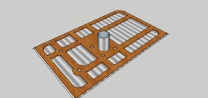
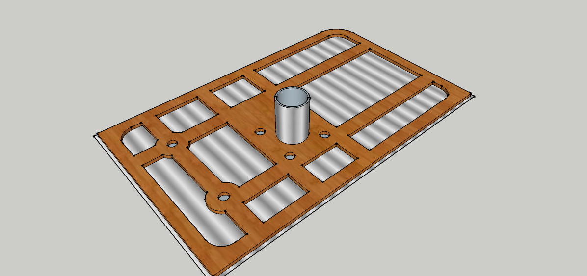
With a CNC router, machine away the plywood to leave complex shapes and struts to give strong, light and complex components. Any mounting holes or slots are accurately placed in seconds. Note how the aluminium body panels are already glued to the formed struts.

Next, a CNC laser cutter swiftly cuts through the aluminium sheet to separate the various components; deliberately exposed flanges can be peened over to increase strength and appearance.

Note that, at this stage, all the teams of tappers and welders have been replaced by a couple of CNC machines. Often the machines are beavering away with no one there at all – might as well turn the lights out then.

So far so good but this technique can be taken so much further.

Back-to-back panels

Panels can be doubled up with wood sandwiched in the middle and aluminium outsides. Immensely strong components are the result and with attractive curved edges if required. For example, a side body panel now strong enough to double as a chassis.

To enable through-bolts to be tightened without crushing the wood there will be plug pairs inside with a star washer in between to further transmit any applied load into the wood.
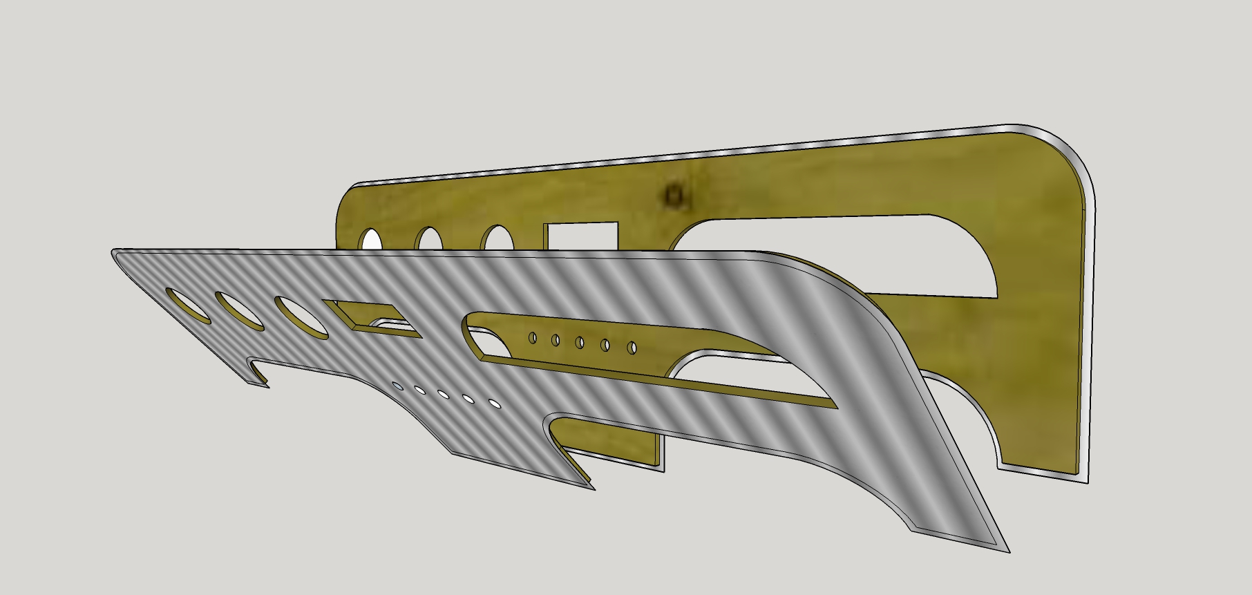
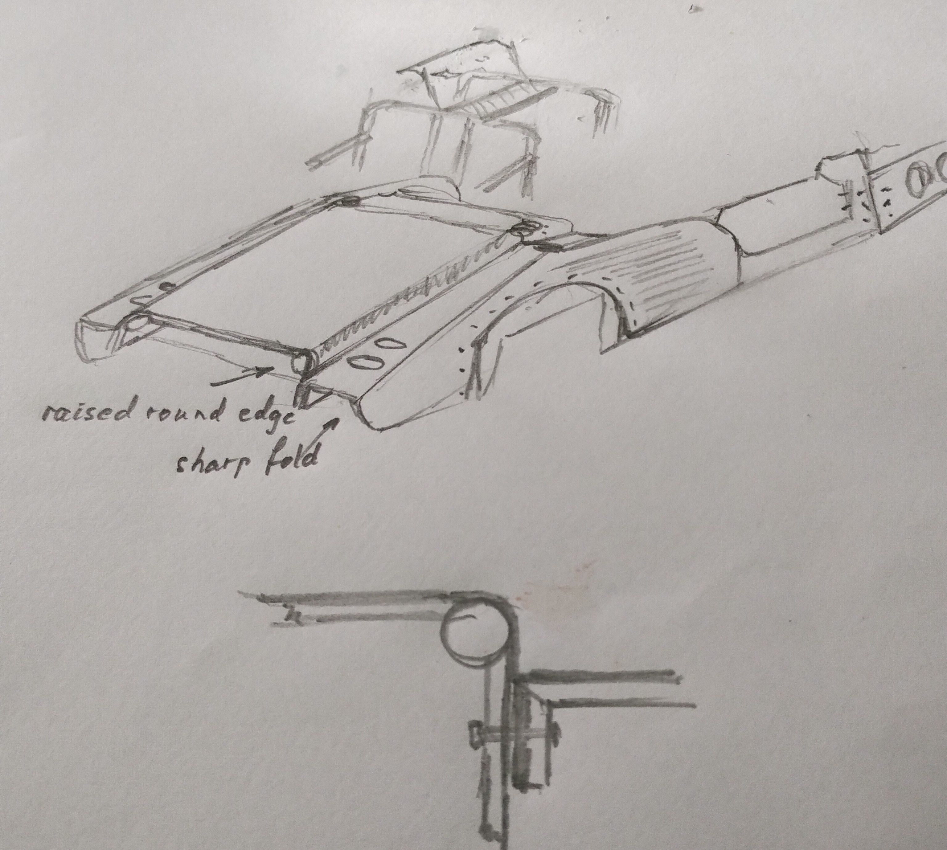
Folds

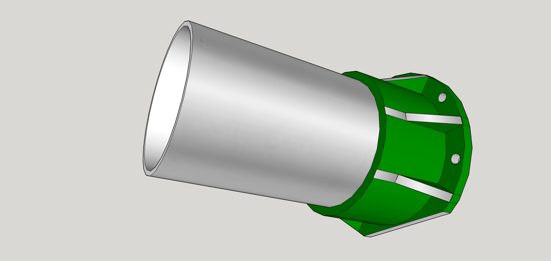
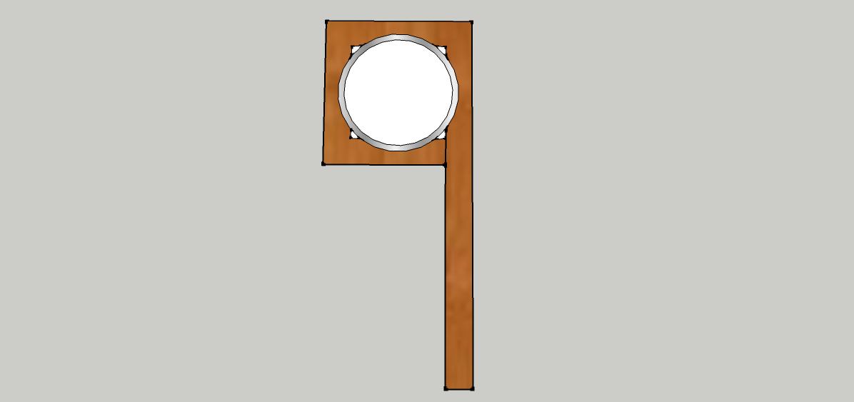
Machine a ‘V’ groove into the wood and the panel can be folded along that line using the aluminium as a hinge. This enables structures to be more than two dimensional and makes seamless direction changes possible. Rounder corners are also possible by wrapping the corner round a tube which is not only attractive but offers a useful conduit for wires, brake lines etc. You’ll see below that all the seams are folded inwards so that when the panels are bolted and glued together the outside finish is clean aluminium.

The fold-round-a-tube concept could be significantly extended. If that tube was part of the steel tubular sub-structure then the added strength of the panels would be significant. For example; the roll bar supports in the rear section would make immensely rigid supports to the rear subframe.

Note that the rounded corner allows room for a press to make the bend accurately and the power allows more choice of cover materials; stiffer ally for example or even stainless steel. Not all the bends have to maximise strength though; a plastic coat is cheaper and allows for interesting printed finishes or even wraps. Interior panels can be leather wrapped even at this early stage in production.

Angles and joins

The basic sports car shape is a box at the back and a tapered front section. This leads to an angled joint, often between separate sections, and this will require an angled plate, or two, to be bolted across the join. As this is usually at the front bulkhead there is scope to make the plates in steel welded to a roll cage/screen frame. If you have to keep it neat, a plate can be fitted right inside the sandwich but obviously it can’t be welded to anything.

Centre console

This centre console has side panels with appropriate slots inside to take flat slats across. With our trusty router we’d machine all the switch holes etc in the flat and then bend the ally to fit slats to slots. Wood veneer on the outside or ally? Decisions. You can see that an expensive looking centre console is actually just a trivial machining exercise done in a few minutes.

The old ways – but obsolete?

I’d start with Mazda MX5 subframes with all the suspensions diff etc attached. From a production point of view having all these components added to the car with a few buzzes of a nut spinner is a huge plus.

Sticking with Mazda theme a Ford Duratec 2.5 four-cylinder engine is the obvious choice. With VVT this engine goes from a docile traffic crawler to a mad screamer, all at a low price.

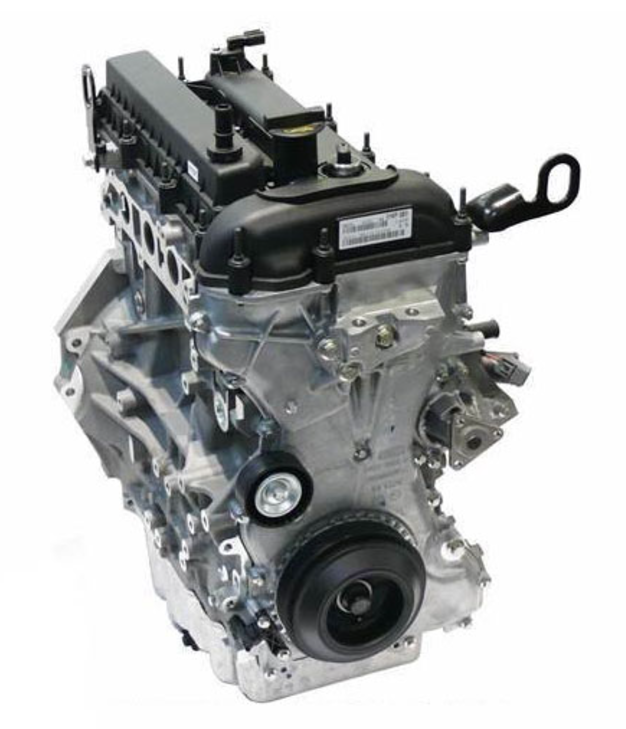
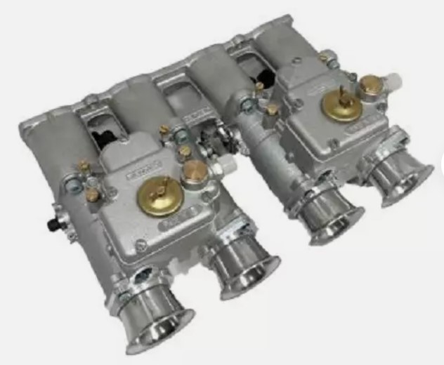
Give it the period look with Jenvey Webber 45 DCOE replica throttle bodies which, along with a few mods, will be good for 240bhp.

Apart from being a perfect engine choice, it already sits on the MX5 subframe and bolts up to one of the best manual gearboxes available. There is a good chance that the standard propshaft will fit too. Supercharging (Sprintex) can add well over 100bhp but that’s hardly needed for a light road car – or is it?

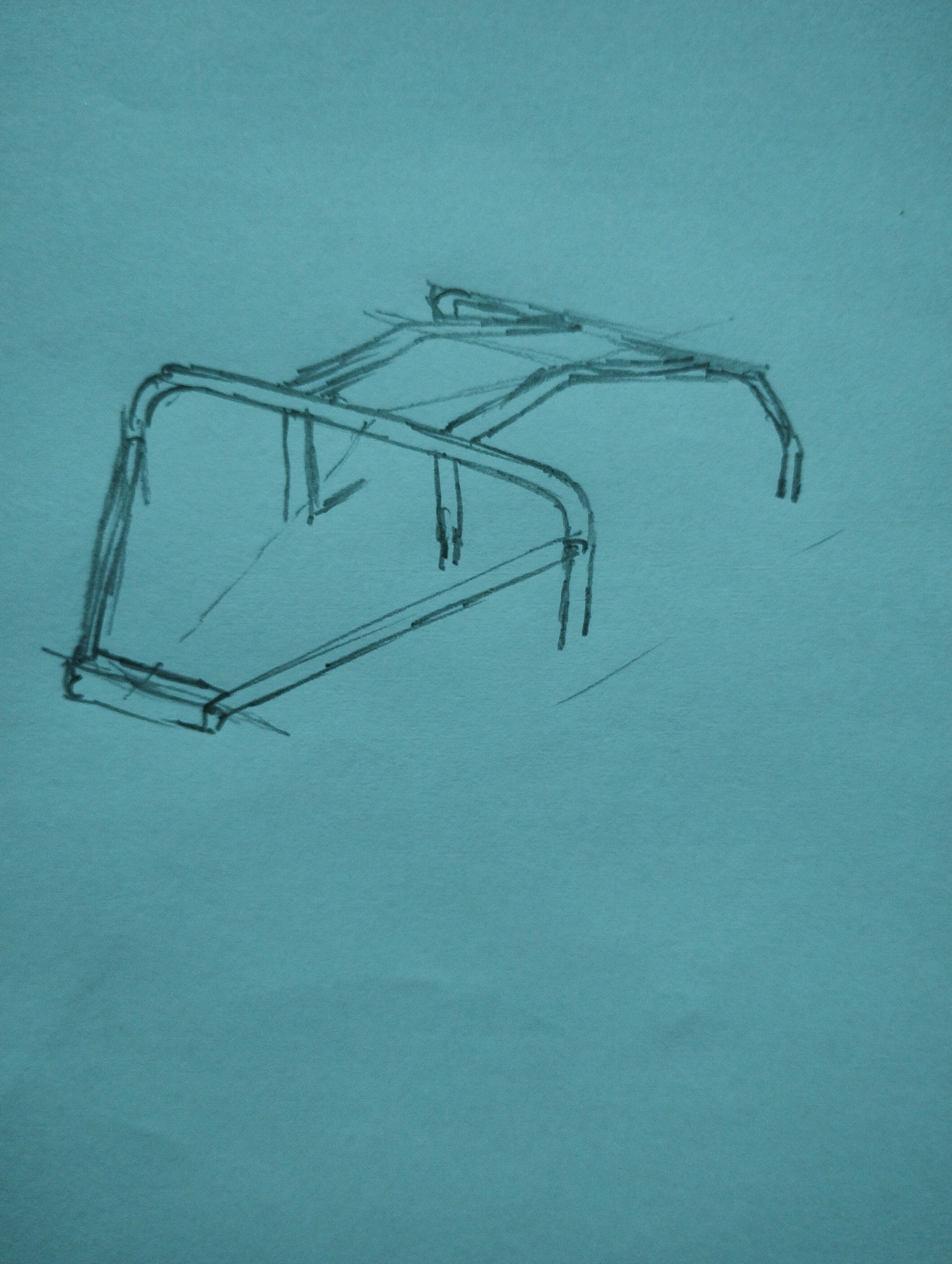
Very fast open top sports cars are downright dangerous. The trouble is you can arrive anywhere very suddenly, and at speed, which catches out other road users and increases the chance of an accident. So, I’d definitely want front and rear roll hoops. I’d go further with connecting tubes down the middle of the car roof to give a radical increase in rigidity. Then I’d do the usual wood and aluminium wrap around the tubes to get a targa top and I’d finish that off with openable and removable polycarbonate roof panels, as sketched previously – instant access for tall drivers at last. Of course, the inside of the roof panel would be machined to take a dash cam, switches and lights – just like a fighter jet then.

Extras – CNC machining already adds huge labour saving value to the panels and this can be taken much further. For example, side panels could have brake lines trapped neatly in the sandwich and the same for wiring too. Pockets for loudspeakers are simple to incorporate; just a few more lines of code for the CNC router. Each panel would become a sub-assembly in its own right and this enables the final assembly of the car to be much quicker and neater.

Just by removing wood air ducts can be pre-machined inside the sandwich and this begs the question; could all the components for a heater be incorporated into the dashboard? The external blower just leaves the heat exchanger to fit. Ducts lead to manually adjustable outlets such as the eyeball jobs seen on Cortinas.

You know that brolly hidden in the door idea? A few seconds extra on the CNC so why not?

The laser cutter can make a complex logo in seconds; polycarbonate backing with press fit LED bulbs completes the job. There are no particular restrictions on size so, for example, a huge logo on the back of the car could double as a brake light.

Wings, cowl, seats, heater etc etc – If you are a manufacturer with these on the shelf for an existing car, that would be a good start! I once saw a classic car that was entirely polished aluminium and chrome; might have been an SS Jaguar. Anyway, it looked absolutely fabulous and that look is possible here.

Electric Vehicles

The incredibly light but strong panels described above are perfect for electrification. It’s all about how the loads are fed into the corners via panels that double as chassis members..

The flat plate concept

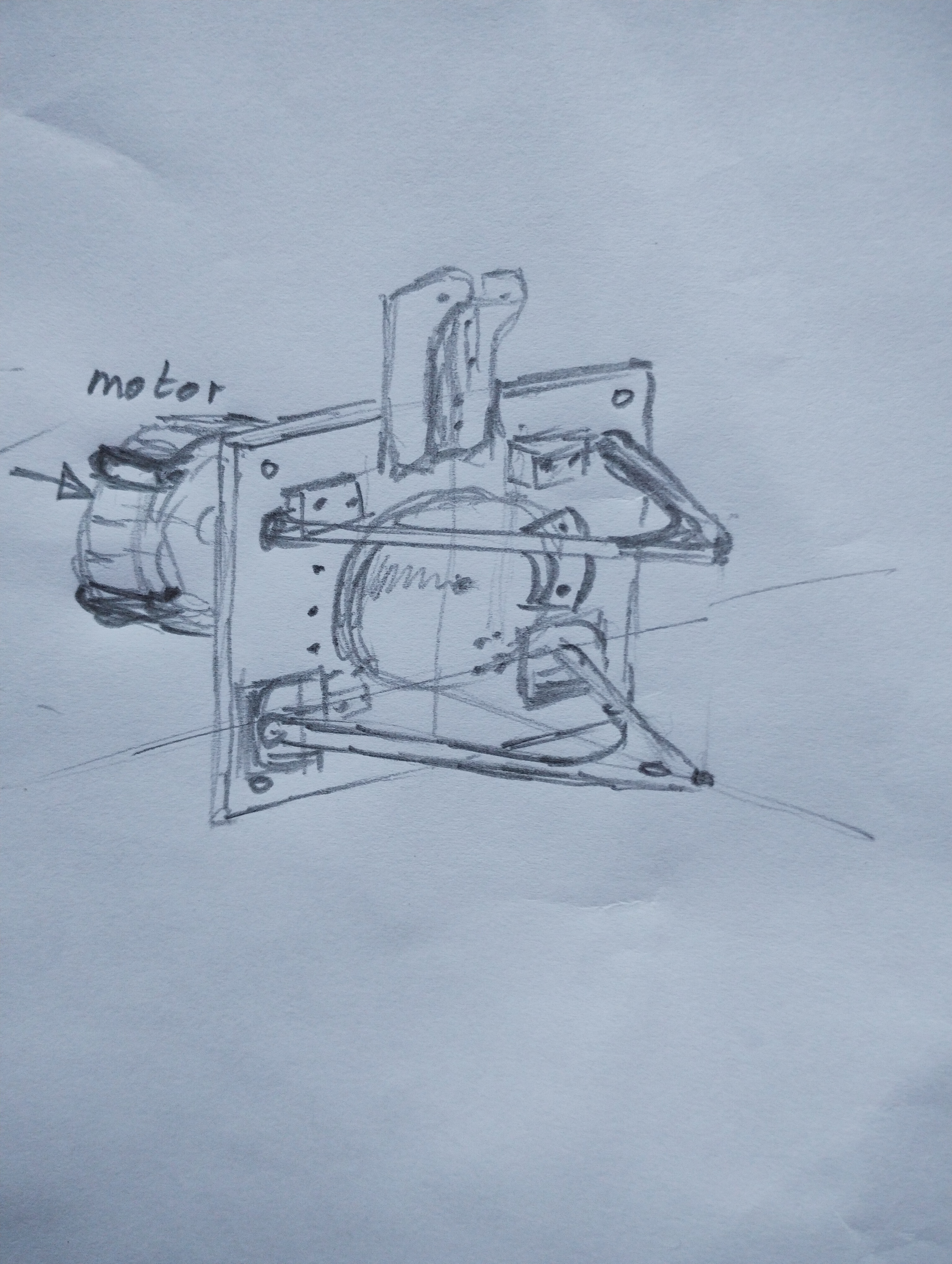
Take any corner of the car and start with a flat plate. On the back of it bolt on an electric motor. On the other side goes a brake disc with its caliper bolted directly to the plate. Unequal length suspension wishbones have mounts bolted to the front and back of the plates and a coilover mounted at the top. That’s about it; all rather neat, simple and cheap, and incorporated beautifully with the body panel which goes between the motor and the plate. Remember, the brake line is already embedded in the body panel so that’s neat too. The motor is brought inboard and protected from the elements. Note the benefits to unsprung weight with inboard brakes. To prevent excess heat from the brake disc being conducted to the motor it will be necessary to space them apart with a coupling in between. The chassis/body panel will also provide some separation and conduct heat away too. Bear in mind that regenerative braking takes away a lot of energy and also that the brake disc can be as big as is needed without having to fit inside a wheel – plenty of space for another caliper if needed.

Talking of cooling; any ally clad panel with Alupex pipe inside (like underfloor heating) would make a cheap oil cooler – not particularly efficient but very neat and dragless too.

Would the plate concept be cheaper to build? Those complex subframes for example – gone. Engine, gearbox, propshaft, diff, all gone. Of course, the neatness of this arrangement easily allows rear-wheel drive or four-wheel drive where 0-60 times under 3 seconds are realistic.

N.B. We still need a deep propshaft tunnel for strength – good place for some batteries. Low polar moment of inertia and all that.

Embedded wires concept – A few motors and battery packs all need heavy wires to connect them. Our flat panels can replace wires with thick aluminium ribbons trapped inside. This could even be like a ring main all round the car; batteries feed in, motors (via inverters) take out, with hardly a wire in sight. Of course, extra strips of aluminium inside body panels all add to the strength; structural wiring! You heard it here first.

Summary – A quickly assembled set of panels make an incredibly light but strong basic body which is so inexpensive it’s hard to see how it would cost more than £2,000, and don’t forget, it does away with a chassis and comes with every mounting hole placed with precision accuracy. Based on an assembly of flat panels it is exceptionally suitable for older style vehicles. Combine all this with the flat plate drive/suspension units and electrification looks like the way ahead.

P.S. Forgive me for trawling through the traditional concepts first but, by contrast, it shows how the electric version is so much more exciting and so delightfully simple that it sweeps away all those old ways of doing things.

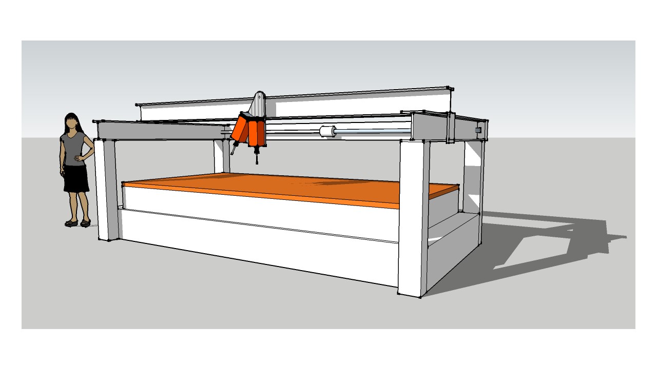
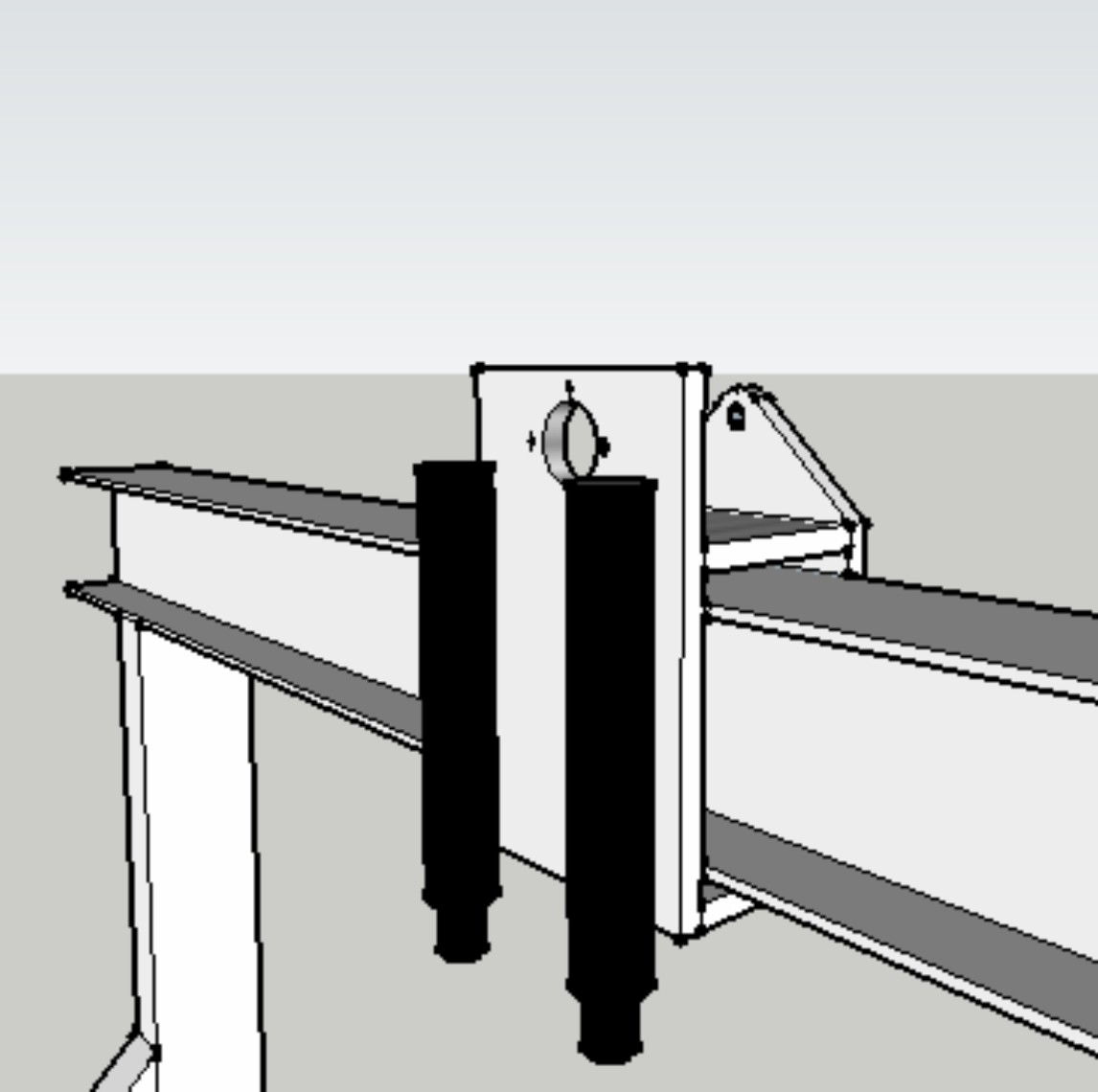
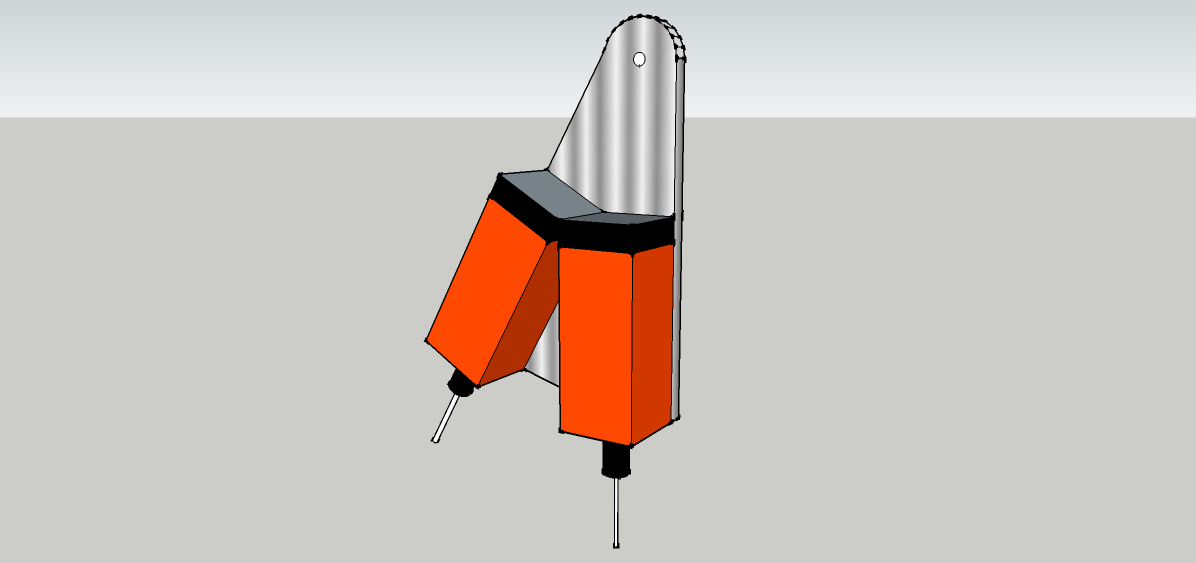
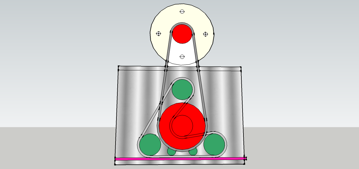
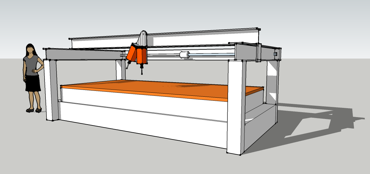
CNC routers – If that’s a new world to you I’d recommend CMS from Italy. I’ve used one with six 20hp router motors and twin tables – an awesome beast.

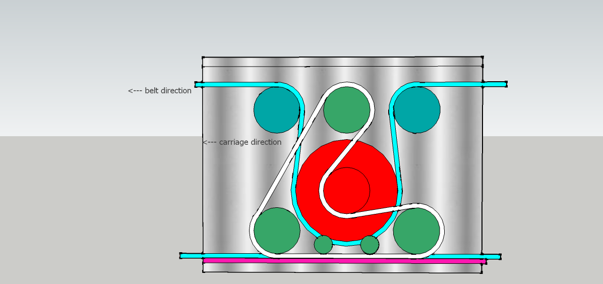
or – here’s one I designed earlier

CNC router – Slide box and tool changer

Aluminium slide box

Aluminium slide box

tilting motor mount

tilting motor mount

Slide box: The basis is a wrap around box of thick aluminium plates enclosing the beam.
Each of the 4 plates has a unique function. The top and bottom plates are for the absolute location of the slide box; Turcite blocks for the heavy downward loads and vibration damping, ball bearing rollers only for lateral location.
One vertical sideplate supports the entire drive mechanism – see picture. The drive motor sits over the top of the slide box and drives the big pulley on the outside. All the rest is inside the web of the RSJ ending up with the toothed belt driving onto the rack with a caterpillar drive to give more tooth contact. This plate is at the back of the machine and also supports a pair of Desoutter AFDK drills which just need a pulse from a 4mm air pipe to set them off on an automatic drilling excursion.
The other side plate supports a swinging plate that holds a pair of angled router motors. These are alternately selected with a push from an air cylinder; the cheapest alternative to a tool changer you’ll ever see.
The tool changer: The top pivot point is in line with each router motor axis so that they both swing into exactly the same position. The pneumatic pusher cylinder is mounted inside the slide box and pushes a peg that goes through a slot – neat huh? Between the motors a round steel plug is pressed into the plate and one of a pair of electromagnets pulls this to lock the plates together (better solutions in comments please).
So there we have a heavy duty industrial quality router with 2 tools and 2 drills; about £20,000 worth if you had to buy one. One could earn a comfortable living with one of these. Not a lightweight project but still DIYable. Don’t get bogged down with cutting, welding and drilling heavy frames; the steel suppliers have all that kit and will make your frame in no time. Just send off your drawings and wait for your cnc router to arrive.
Levelling the beam: There must be a few ways to do this other than sending it away for precision grinding.
A small steel block with a laser on it will show a dot moving up and down a target to reveal the bumps which will respond to a light touch of an engineers scraper.
When the beam is true adding hardened steel guide bars will provide the perfect flat finish.
Panels: Professional machines come with expensive steel panels. As the central box chassis needs to be stiff and straight use MDF panels bolted to the steel to make it neat and strong too. Hammerite paint on MDF is remarkably durable and will keep it all looking very tidy.
Bellows: With a rectangular box sliding on the RSJ there will be no problem in adding bellows to make the machine the ultimate in tidiness and this will be no bad thing for the unlubricated Turcite slides.
For further reading try following http://www.mycncuk.com -a fount of CNC knowledge- and please criticise or add ideas for improvements in comments.

More on this topic in LIST OF POSTS

CNC router – Caterpillar drives

enclosed reduction drive click to enlarge

enclosed reduction drive
click to enlarge

Differential belt drive

Differential belt drive

Driving both sides of a wide gantry present some awkward problems. Coupled long ball screws are expensive and prone to whipping and synchronised stepper motors on each end don’t always step in time and crabbing can occur. The caterpillar drive shown here (top left) for the slide box on the X-axis is intended to enable a timing belt to engage with a rack with the arrangement incorporating a low cost reduction drive.

The X-axis beam is supported by a slide box on each end and each one contains the caterpillar drive (top right). A single drive shaft, with a pulley on each end, pulls the slide boxes up and down the Y axis via long timing belts. The drive boxes contain reduction drives which finally engage with a rack.  We call them caterpillar drives because the drive belt engages with the rack just like a tractor laying its track on the ground. Note that the pull on the belt is in the same direction that the slide box moves and that there is a differential action with the belt moving much faster.
With a couple more pulleys the main drive belt at the top can be brought down to run under the red drive pulley and just above the lower run. Thus the belt can be made to lie, and slide along a slippery nylon bed rather than flap in the air.

More on this topic in LIST OF POSTS

DIY industrial CNC router

CNC heavy chassis

CNC heavy chassis

Cheap computers and software have brought CNC machining within the realms of DIY.


Some smaller routers are not much more than toys but for a machine that can commercially earn its keep we need some size and the ability to hang more tools.
So here we have something much bigger and heavier without increasing the cost to anything like a professionally made router.
Size: In order to machine round the outside of a standard 8’x4’ sheet we’ll need a long and strong X-axis. A heavy steel RSJ will resist the tendency to sag under the weight of two 4.5kW router motors and two drills. Of course a machine that holds multiple tools is ultra productive but also very expensive; usually that is.

We can get to two router motors and two drills pretty cheaply with the tipping tool changer concept. More details here 

The neat thing about an RSJ is that it is not only cheap but the ‘I’ section enables us to put drive gears and the drive rack neatly inside the web.  more details on drives here:
Torsional rigidity is not a strong point but is easily enhanced by welding a heavy tube inside one of the webs. Steel can pick up vibration so filling the tube with heavy chain and oil will make a cheap but effective damper. You only get really smooth finishes on a machine that is well damped.
Z axis: You could buy an off the shelf Z slide and hang that off the X axis for a conventional and simple layout but the logic of that is debatable. When machining flat boards etc there is very little Z movement so it would be better to put the Z under the table so that the two major movements – X and Y – are as light as possible. The Z frame (the whole bed) is raised like a garage car lift with 4 chassis mounted screw posts rotating to drive ball nuts on the frame. Unlike the continuous chain of the garage hoist a short timing belt for each screw connects to one of a pair of drive spindles which are both driven by a central belt and the stepper motor. This way we get reduced belt stretch and a built in reduction drive. This layout enables a much bigger Z travel – 3D modelers note – and makes a fast and responsive machine with a tidy uncluttered look. Air balancing means there would be no heavy lifting for the Z stepper motor.

This unusual configuration has a lot of advantages. The sketch above doesn’t show the tractor drives or the box slides (one for the tool head and 2 to hold up the X-axis beam) which are described in detail here.
The rear mounted drive shaft drives the two differential caterpillar drives that power the Y-axis.

Panels: MDF – easy to cut, cheap, noise suppressing and remarkably robust when painted with Hammerite.

Snags?
Weight: Chassis needs heavy welding skills and reasonable accuracy.
Z-axis: Quite elaborate 4 pillar lift mechanism with guides.

The advantages.
Size: Scaleable to industrial size. Pictured as 2m x 4m here.
Visibility: Whole work table visible without moving obstructions like gantry legs.
Safety: Work table has no sideways movement. No pinning accidents.
Space saving: No sideways movement of table so roughly half the footprint.
Convenient: Router motors present themselves right to the edge of the table.
Accurate: Very solid construction gives accuracy and good machining finish.
Neat: Hollow beams accommodate wires, lights and control panels.
Responsive: Weight of Z-axis is removed from the X and Y axes.
Large Z-axis: Big range possible – good for carving.
Short Y-axis: Single stepper motor drives both ends of X-axis beam so no crabbing.

…. and isn’t it the neatest CNC router ever?

…. and check out the LIST OF POSTS for more like this

Hybrid 3-wheeler – structural panels

Eco-car structural bulkheads.

light and strong

light and strong


Aircraft grade birch plywood stuck onto an aluminium sheet has been CNC machined away to leave struts for load distribution and pockets for plug inserts. Loads are distributed by the remaining integral struts.


CNC machined panels

A mirror image version will then be glued on top –wood to wood- and the outside aluminium edges peened over to leave a solid looking panel (but largely hollow inside) which will not only look good with complex curves but be very strong and light. Any big holes in the panel will have the edges peened over too. Peening can be largely automated with a CNC guided rotating roller head.
Heavy loads from components bolted to the panel are fed in via plugs inserted into machined pockets so that any through bolts can’t crush the wood structure when tightened. The plugs are fitted in pairs with a larger star washer in between so that the sharp edges crush into the plywood to give even more load transmission.
Being CNC machined, identical complex panels can be produced quickly and with minimal labour cost. It pays dividends to design complexity out of the car and into the panels. Padded leather panels, a headrest for example, can easily be bolted up to the bulkhead as can other trim items.

Front and rear bulkheads in our car will be connected by 3 aluminium tubes. They will be joined to the bulkheads by cast ally brackets where the tube end is expanded and glued by a tapered collar pressed into each end.


The picture here shows how a side panel wraps the tube to make an immensely strong beam affording maximum side impact protection and, of course, a nice wide arm rest as well. The folding is achieved by machining ‘V’ grooves through the plywood leaving the aluminium skin to be a bent hinge line. A more complex shape to the groove can make rounder corners too.
.
The inspiration for much of this comes from two great car designers. Colin Chapman made racing car bulkheads from opposed metal sheets with peened holes and edges for rigidity. Alec Issigonis with his Morris Minor design used a complex bulkhead to mount suspension, shock absorbers, steering rack, battery box, pedals and more. We shall do the same.
No doubt the car will be strong, stiff and light but there is more to an eco-car than that; it must come at an affordable price and these techniques get us there all in one hit. In fact the car is so simple that anyone with a modest workshop and access to a CNC router could make one. Maybe a good base for a schools project?
Ultra strong and light complex panels like these will have many other uses. Paired frames for a motorcycle and a gyrocopter immediately spring to mind. In higher volume applications the plywood core can be precut with a waterjet cutter and then glued between the precut aluminium sheets.

More on this topic in LIST OF POSTS